
A partially open gate valve is the wrong tool for modulating steam: high-velocity steam impinges on the unseated disc face, erodes the seating surfaces, and drives a non-linear Cv curve that no process operator can trim with repeatable accuracy [S1][S3].
Steam amplifies every failure mode: saturated steam at the vena contracta flashes when static pressure drops below saturation pressure, the resulting bubble collapses have been measured at peak conditions around 17,500 °F and 14,700 psi, and that micro-jet energy pits the gate edge and downstream seat within hours rather than weeks [S2].
How a Gate Valve Geometry Creates the Problem
A gate valve is a linear-motion isolation device: a multi-turn stem lifts a wedge or slab out of the bore, and the seat-to-disc contact only happens at full closure [S4]. The disc moves perpendicular to flow, so any opening below 100% leaves a sharp-edged obstruction inside the bore, and the resulting annular gap behaves as an uncontrolled orifice with a vena contracta directly downstream of the gate edge [S2][S4].
That geometry is acceptable for water and steam isolation because the disc clears the bore completely in the open position, giving the line its full pressure class and a near-zero flow restriction; a gate valve in full-open service is essentially a section of pipe [S1][S4]. The moment you park the disc at, say, 40% lift, you have a de-facto orifice plate with a sharp edge, and the steam does the rest of the work for you in the wrong direction.
The Five Failure Mechanisms in Steam Throttling
Mechanism 1, seat and disc erosion: high-velocity steam carrying entrained moisture or condensate droplets cuts the seating surfaces like a sandblaster, and once the seat loses its lapped finish, the valve can no longer achieve bubble-tight shutoff when you do need it [S1][S3]. Mechanism 2, mechanical vibration: the turbulent jet downstream of a partially open gate leaf excites the disc, stem, and bonnet, producing a metal-on-metal clanging that was historically misdiagnosed as gravel passing through early hydro gate valves [S2].
Mechanism 3, cavitation and flashing: at the vena contracta, static pressure falls to its minimum, and if that minimum drops below the saturation pressure of the steam, the fluid flashes; the subsequent re-pressurization collapses the bubbles violently, with peak micro-jet conditions around 17,500 °F and 14,700 psi, a regime that drills pits into the disc edge and the downstream body [S2]. Mechanism 4, thermal cycling: superheated steam throttling can deliver 100-300 °C of temperature drop across a single valve, and that swing mechanically distorts seats that were machined to a tight tolerance at room temperature [S3]. Mechanism 5, non-linear Cv: the relationship between gate lift and flow is highly non-linear, so a small hand-wheel change near 30-60% open produces a large flow swing that operators cannot trim to a stable setpoint [S1][S3].
Gate Valves vs Globe Valves vs Control Valves on Steam
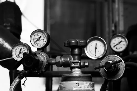
On a saturated-steam line at 10 bar and 184 °C, a wedge gate valve used in partial-open modulation will typically lose bubble-tight shutoff within weeks, whereas a properly sized globe valve on the same duty stays tight for its full service interval [S1][S3]. The comparison is sharper on the key criteria process engineers weigh:
Modulation accuracy: a globe valve's plug-and-seat geometry gives a near-linear installed Cv across 30-80% lift, so a 4-20 mA control loop can hold ±2-5% of setpoint; a gate valve's curve is so steep in the 20-50% lift band that loop tuning is essentially impossible [S1][S5]. Erosion resistance: globe valves direct the flow onto the plug face parallel to the stem axis, not perpendicular to a sharp edge, so seat life is typically 5-10x longer than a gate valve on the same steam duty [S1]. Cavitation margin: a single-stage globe on clean steam generally tolerates a pressure drop of about 30-40% of inlet pressure before cavitation damage starts, and multi-stage or angle-pattern designs push that limit higher, while a gate valve cavitates the moment its vena contracta drops below saturation [S2][S5].
If the requirement is on/off isolation of a steam header, the gate valve is the right pick, and API 600 / API 6D gate valves are the industry default for that service. If the requirement is to drop 6-10 bar of pressure and hold 200 °C steam at a stable mass flow, a globe-style control valve sized with the correct Cv and a hardened trim is the correct pick.
When a Gate Valve Can Be Parked Near-Closed
There is one narrow exception. Several manufacturer guides permit a gate valve to be used as a throttling device only when the gate is at least 90% closed, because at that position the flow area is small enough that vibration and seat cutting are limited to short-duration, infrequent operations [S1]. This is occasionally done on warm-up duty or as a last-resort manual bypass on a small steam line, never as a continuously modulated setpoint.
The throttling knife gate valve is a separate design, developed from pulp-and-paper stock valves, and it is engineered for sustained throttling on water and low-pressure slurry; it is not a drop-in replacement for a steam control valve, and steam service is outside its standard envelope [S2]. For steam specifically, the seat materials, body geometry, and stem packing of a throttling knife gate are not specified for the temperatures and flashing loads that saturated or superheated steam imposes.
What to Specify Instead for Steam Throttling
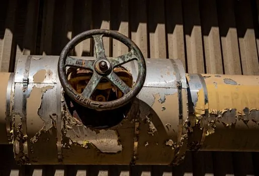
For modulated steam duty, specify a globe-pattern or angle-pattern control valve with a characterized trim (equal-percentage or linear), a stainless or Stellite hard-faced seat, and a packing set rated for the steam temperature, typically graphite or PTFE for saturated steam and flexible graphite for superheated service above 400 °C. Add a steam trap and steam separator upstream to remove entrained moisture, since dry steam dramatically extends seat life on any modulating valve. [S3]
On a control loop driven by a flow measurement on the steam line, the typical setpoint stability achievable with a properly sized globe control valve is within ±2-5% of mass flow, while a gate valve on the same loop is un-tunable because the small-lift portion of its Cv curve behaves as a binary on/off device. The flow meter itself does not need to change; the issue is the trim element upstream of it.
Operating Practices That Reduce the Risk If a Gate Valve Stays in the Line
Three habits limit the damage when a gate valve must remain in a steam line for legacy reasons. First, run fully open in normal service and only crack the gate for short warm-up ramps, never for hours of modulation. Second, schedule a seat inspection every 6-12 months on any gate valve that has seen partial-open service, since leakage past the seat is the first symptom of erosion damage. Third, pair the gate valve with a downstream steam trap to keep condensate from forming in the body cavity, because water slugs in a hot gate accelerate seat pitting. [S3]
For a process engineer who has just been asked to "use the existing gate valve" to control steam flow, the cheapest correct answer is to refuse the modulation duty and to install a properly sized globe or control valve in parallel, leaving the gate valve as a full-bore isolation device; the more reliable operation and the avoided seat-replacement outages pay back the new valve in a single planned shutdown.
Trackable signals worth watching over the next 6-12 months: any new API 600 or API 6D gate-valve technical bulletin explicitly tightening the partial-open prohibition for steam service, and any major utility moving from gate-valve warm-up bypasses to dedicated globe or angle-pattern warm-up valves on 100+ MW boiler starts.
For related coverage, see Digital twin of a battery cell production line: architecture, defect targets, and.