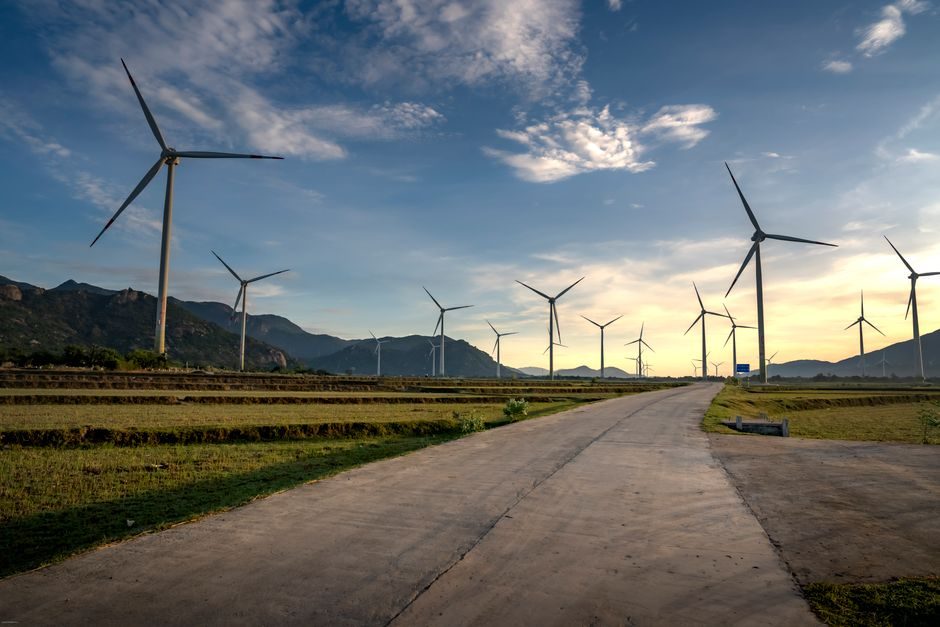
Wind turbine main-gearbox smart manufacturing now converges on three measurable pillars: a 1.5 MW closed-loop back-to-back test stand running 578,000 lb-ft at 18 rpm on a LabVIEW-controlled FieldPoint DAQ, SCADA-fed condition monitoring that streams vibration and lube-oil temperature into a central database, and OEM-run intelligent quality lines such as Goldwind's, backed by 3,000+ R&D engineers (29%+ of headcount) and CNY 2.8 B R&D spend in 2024 [S2][S3].
Gearbox acceptance still targets the standard WT envelope — low-speed shaft at 30-60 rpm, high-speed output raised to roughly 1,200-1,500 rpm for the generator — so the test bed, the gearbox under test, and the SCADA analytics layer must be sized to that exact speed step-up ratio [S1].
The 1.5 MW Back-to-Back Test Bed: Specs and Limits
The reference 1.5 MW wind-turbine gearbox test stand at GE Transportation (Pennsylvania) is sized to simulate 578,000 lb-ft of torque at 18 rpm input, matching the field loading a production gearbox sees inside a 1.5 MW turbine nacelle [S3]. Two identical gearboxes are coupled input-shaft to input-shaft; the slave unit runs in reverse to act as a mechanical speed/torque source, while a 1.5 MW motor-generator on the test-unit's output shaft absorbs power as a programmable load [S3].
Drive and load are tied through a common DC bus on solid-state inverters, so the regenerative energy from the load motor recirculates back into the drive — a closed power loop that GE supplements with a 600 kW grid-tie converter to cover system losses [S3]. Two GEB-16A4 traction motors (originally designed for mining trucks and locomotives) supply the speed and torque envelope; their built-in dynamic-braking stages emulate generator loading without a separate dynamometer [S3].
Acquisition runs on NI FieldPoint with custom LabVIEW software, and the user interface is intentionally simple: GE test technicians — not control engineers — run acceptance, so robustness and short learning-curve matter as much as raw sample rate [S3]. Captured channels include vibration, acoustic emission, lube-oil temperature, and gear-mesh phase, which feed the same SCADA databases the field fleet streams into [S1][S3].
SCADA as the Quality and Condition-Monitoring Backbone
SCADA-based condition monitoring treats the turbine as a continuously sampled asset: vibration, acoustic, lube-temperature, and gear-mesh data from the nacelle are pushed to a central database, where trend analytics flag bearing and gear faults before they become catastrophic failures — a critical capability given the high cost and downtime of WT maintenance [S1].
On the factory side, the same data backbone feeds the intelligent quality management systems OEMs use to certify each gearbox before shipment — often pairing SCADA telemetry with smart camera-based visual inspection of gear teeth and bearing surfaces. Goldwind's smart-manufacturing programme explicitly couples "intelligent quality management standards" to a green supply chain, with the stated goal of making clean-energy production "more efficient, reliable and affordable" [S2].
The measurable edge: SCADA analytics convert a 1.5 MW gearbox acceptance run — vibration spectrum, acoustic signature, lube-oil temperature curve, gear-mesh timing — into a per-unit digital fingerprint that lives in the same database the field turbines report into, so fleet-wide learning improves single-unit acceptance [S1][S3].
Closed-Loop Mechanical Design: Couplings, Mounts and Alignment
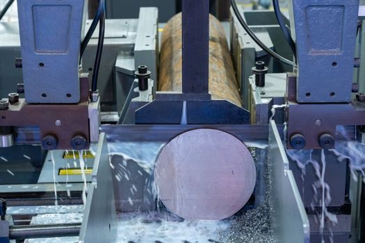
The hardest mechanical problem is not the 1.5 MW power level — it is moving the unit-under-test (UUT) in and out fast enough that the test bed stays productive. GE solved alignment with a sliding gear coupling (Ringfedder hydraulic shrink-disc to the UUT input shaft) plus locating locks on screw jacks, and tapered pins dropped between couplings to support the suspended mass while bolts transmit torque [S3].
Both gearboxes are normally mounted on elastomeric pads to cut noise and vibration; the test stand replicates that compliant mounting on a heavy fabricated steel base sitting on isolation pads, a structure installed in roughly two days that delivers the rigid, low-vibration environment the driveline needs while still isolating the cell from the wheel-motor assembly line [S3].
Cooling and acoustic isolation are handled by enclosing the drive motors in a noise-attenuating fence connected to a forced-air cooling loop, separating test-cell acoustics from the surrounding production hall — a layout detail that determines whether vibration and acoustic acceptance data are usable at all [S3].
OEM Smart-Factory Footprint: Goldwind as the Reference Data Point
Goldwind's smart-manufacturing programme pairs steel-concrete hybrid tower design with deep-sea floating offshore, large-megawatt turbines, ultra-flexible blades, load-control, and a simulation software platform as its R&D investment axes [S2]. Goldwind's disclosed R&D scale includes 3,000+ R&D technicians (29%+ proportion of headcount), 7,300+ technology patent applications, 1 national-level enterprise technology center, 47 provincial-level scientific research qualifications, 3 postdoctoral workstations, 42 national scientific research qualifications, and 70 national key research and development projects [S2].
2024 R&D spend was CNY 2.8 B+, a capital base large enough to underwrite dedicated smart-gearbox assembly cells, in-line torque and vibration test, and SCADA-linked quality analytics that ride on the same digital thread used for tower and blade production [S2]. The investment mix — flexible blades, large-megawatt turbine design, simulation platform — is also a signal that gearbox smart-manufacturing will be specified against the next step-up in torque density, not the 1.5 MW class alone [S2].
Selection Criteria: What a Smart Gearbox Line Must Deliver
A modern wind-turbine gearbox smart-manufacturing cell should be evaluated against four hard criteria. (1) Test-bed power class: 1.5 MW closed-loop with regenerative DC bus and a 600 kW grid-loss make-up converter is the documented baseline for 1.5 MW class acceptance [S3]. (2) Torque/speed envelope: must reach 578,000 lb-ft at 18 rpm input to faithfully reproduce nacelle loading [S3]. (3) Data plumbing: SCADA-grade DAQ (NI FieldPoint / LabVIEW class) streaming vibration, acoustic, lube-oil temperature, and gear-mesh phase into a central database that the field fleet also writes to [S1][S3]. (4) Mounting and handling: elastomer-pad-mounted gearboxes, sliding gear coupling with hydraulic shrink-disc, and a relocatable steel base on isolation pads — so the UUT can be swapped in days, not weeks [S3].
OEMs that satisfy all four — Goldwind-class R&D scale plus the 1.5 MW closed-loop test architecture — are positioned to ship gearboxes whose digital fingerprint is comparable across units and across fleet [S1][S2][S3]. Vendors that only offer a test stand without the SCADA back-end, or a smart-factory label without a documented torque/speed envelope, leave the buyer reconciling two disconnected quality systems.
Limits, Failure Modes and Watch-Items
The 1.5 MW test bed is a back-to-back mechanical loop, not a hardware-in-the-loop rig: it physically loads the gearbox, so any test-cell failure (coupling mis-alignment, isolation-pad resonance, motor over-temperature) becomes a real driveline event [S3]. Acoustic interference from the surrounding wheel-motor assembly line and the lack of a traditional power-isolation foundation had to be engineered around with a fabricated steel base and motor enclosures — these are recurring pain points for any nacelle driveline cell placed inside a larger vehicle-production hall [S3].
SCADA-based condition monitoring is only as good as the data hygiene upstream: garbage in (missed timestamp sync, low-resolution vibration channels) means late or missed fault calls on expensive gearboxes [S1]. And smart-factory disclosures that lean on headcount and patent counts — Goldwind's 3,000+ R&D staff and 7,300+ patents — are scale indicators, not gearbox-yield or field-reliability proofs; buyers should still pull per-unit acceptance data, not just R&D totals [S2].
Trackable next signals: OEM disclosures of test-bed power steps above 1.5 MW for next-gen 8-16 MW nacelle drivelines, public SCADA datasets large enough to benchmark gearbox digital fingerprints across fleets, and the first widely cited standard or specification tying closed-loop back-to-back test architecture to gearbox qualification criteria.
For component-level specifications, see turbine flowmeter.
For related coverage, see Battery Pack Manufacturing Process: Cell-to-Pack Flow, Module Topology and QA Stack.