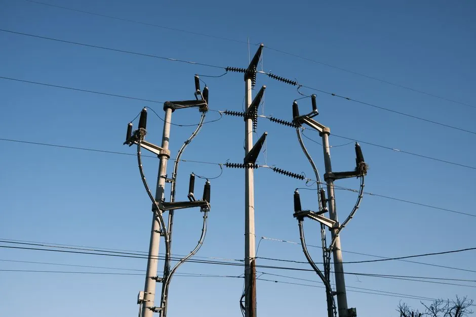
A battery- or busbar-harvested wireless module bolted to a 6-10 kV busbar is a passive dielectric load on the conductor system; it does not ionize gas, overheat insulation, or create voids, so by itself it cannot initiate partial discharge [S4][S5].
Partial discharge is a localized dielectric breakdown that only partially bridges the gap between conductors when the local electric field exceeds the local withstand voltage of a void, contamination layer, or insulation defect [S2]. More than 85% of medium-voltage insulation failures are preceded by detectable PD activity weeks or months before catastrophic breakdown, but the root causes are voids, moisture, dust, sharp edges, and aged epoxy, not the sensing electronics [S3].
What actually generates PD on an MV busbar
PD on a medium-voltage busbar develops in five recurring patterns: internal discharges inside micro-voids in cast-resin or epoxy insulation, surface tracking across contaminated busbar supports, corona at sharp edges or improperly crimped lugs, contact discharge on floating metallic hardware, and gas-phase discharges where SF6 density has dropped or dry-air GIS has lost pressure [S2][S5]. Each mechanism requires a localized electric field strong enough to ionize a small region of insulation, gas, or contamination; the high-frequency current pulse and the resulting electromagnetic, acoustic, thermal, and chemical by-products are the measurable signatures used by monitoring instruments [S2].
The flashover of part of the insulation system happens where V_withstand of the local region C2 is lower than the applied field, even though V_withstand of the surrounding bulk insulation C1 and C3 is still adequate, which is why a single busbar can run for years before a defect site evolves into a fault [S2].
Where a wireless sensor fits, and where it does not
A correctly specified wireless module for busbar mounting is a small, sealed dielectric package with antenna, sensor front-end, and energy harvester; its contribution to the local field is the added insulation thickness, not a field-enhancing protrusion [S1]. IoT-based microclimate monitoring work on switchgear cells has shown that the sensor package itself is treated as a passive enclosure, with the maintenance value coming from tracking humidity, dust accumulation, and temperature, the same three drivers that initiate PD inside the cell [S1].
Where the wireless sensor becomes a PD contributor is in three failure modes: an unshielded antenna tip acting as a sharp protrusion, a power-harvesting coil or CT clip that physically distorts the equipotential lines, or a battery pack with sharp corners pressed against a phase barrier. None of these are intrinsic to wireless sensing; they are mechanical-packaging defects introduced at install time, and the same defects would create PD on any bolted-on accessory [S4][S5].
Detection options if a sensor is the goal, not the cause

Modern MV PD monitoring stacks three sensing channels, each tuned to a different by-product: UHF couplers for the 300-3000 MHz electromagnetic emission, TEV (transient earth voltage) probes for the HF pulse that leaks through the switchgear enclosure, and ultrasonic acoustic emission sensors for the 20-300 kHz pressure wave [S3][S5]. A combined UHF + TEV + ultrasonic instrument with a 100-5000 pC measurement range, ±10% charge accuracy, and IEC 61850 or Modbus RTU output is the typical architecture specified for new builds and retrofits on 3.3 kV to 36 kV metal-clad switchgear [S3].
For online MV GIS specifically, UHF and TEV remain the dominant methods, while acoustic emission is most useful for pinpointing the defect location once UHF has flagged a zone; SF6-insulated bays generate corrosive HF and SO2F2 by-products during PD activity, so any sensor in the gas compartment must be rated for those decomposition chemistries, while dry-air GIS produces only non-toxic by-products and relaxes the chemical-resistance requirement [S5].
Selection criteria for adding wireless PD telemetry to an existing MV busbar
The first decision is whether the sensor must operate in the gas compartment, on the busbar surface inside a duct, or only on the outside of the switchgear enclosure, because the dielectric, thermal, and contamination ratings differ sharply across these three zones [S5]. The second decision is the sensing principle: a wireless UHF antenna inside the cell can pick up PD pulses directly, but a wireless TEV sensor on the outer skin of the cubicle only sees the leakage pulse and is more susceptible to external noise from variable-frequency drives in the same room [S3]. The third decision is power: energy harvesting from the busbar field, a long-life lithium primary cell, or a supercapacitor charged from a small CT, with each option trading maintenance interval against installed bulk [S1].
For most 6-10 kV indoor metal-clad retrofits, a wireless TEV or UHF sensor with an IP66 enclosure, surface-mount adhesive or magnetic mount that does not penetrate the cubicle wall, and a sub-GHz or LoRaWAN backhaul is the lowest-risk configuration, because it adds no conductive path into the live compartment and no mechanical protrusion on the busbar [S3].
Comparison: passive wireless sensor vs UHF/TEV/ultrasonic PD instrument
On measurement sensitivity, a permanently installed UHF coupler inside the switchgear cell detects PD pulses of a few pC, while a wireless surface-mount TEV sensor typically resolves 10-50 pC and an external ultrasonic sensor is useful for localization rather than first detection [S3][S5]. On installation invasiveness, a wireless sensor on the cubicle exterior is a non-invasive retrofit, an internal UHF coupler requires a dielectric window or hatch, and an ultrasonic contact sensor needs a clean acoustic-coupling path [S3]. On data, a wired IEC 61850 PD instrument streams continuous waveform and phase-resolved PD patterns to SCADA, while a wireless module typically reports alarm thresholds, RMS trend, and periodic histograms over LoRaWAN or cellular IoT [S3]. On cost and downtime, the wireless module wins for brownfield sites where opening the cell is not an option, but the wired UHF/TEV/ultrasonic stack wins for new builds where continuous waveform data is required for trend analysis [S3][S5].
Standards and thresholds that govern the answer
IEC 60270:2025 is the reference for charge-based partial discharge measurement terminology, quantities, and test circuits, and is the standard most often cited when specifying pC sensitivity and calibration of the instruments that the wireless sensor would complement [S4]. Online PD detection on metal-clad switchgear operating above 2500 V is the practical lower bound for where the wireless sensor concept becomes economically justified, because below that voltage the failure rate and consequence are not enough to justify continuous monitoring [S9].
Field data from a UK utility evaluation of 191 33 kV cables over a two-year period shows a strong link between initial PD severity rating and two-year failure rate: less than 2% of GREEN-rated cables failed, less than 21% of AMBER-rated cables failed, and less than 40% of RED-rated cables failed, which is the kind of trending data a wireless module is built to surface continuously rather than at scheduled walk-downs [S2].
Limits, failure modes, and what the wireless sensor cannot see
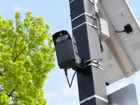
A wireless sensor mounted on the outside of a cubicle cannot directly image a void inside a cast-resin bushing, because the UHF signal is attenuated by the steel enclosure, and the TEV pulse is filtered by the barrier; it only sees the leakage signature, so a negative reading does not prove the absence of PD, only the absence of detectable external coupling [S3][S8]. A wireless module powered by a harvester that fails silently will leave the busbar unmonitored until the next manual check, so any wireless PD telemetry deployment needs a heartbeat, a battery health channel, and a clear alarm on loss-of-comms, not only on PD threshold breach [S1].
For internal PD inside MV GIS, especially SF6-free designs, the wireless sensor cannot replace a windowed UHF coupler or an internal acoustic sensor, because the dry-air dielectric and the optimized solid-insulation geometry suppress the external TEV signal below the noise floor; a wireless module on the tank wall is a status and trend channel, not a primary PD detector [S5].
Track three signals before retrofitting wireless PD modules on a live MV busbar: the existing cubicle's PD baseline measured with a portable TEV/UHF instrument, the failure history of any busbars in the same switchroom, and the maintenance interval at which the wireless sensor's battery or harvester is expected to need replacement, because that interval sets the actual cost per monitored year [S3][S8]. For a deeper look at how wireless telemetry modules are specced for harsh electrical environments, the wireless module reference page covers the electrical and mechanical ratings that matter most, while related guidance on stop-circuit and switching hardware per IEC 60204-1 is covered in Emergency Stop vs Emergency Switching Off per IEC 60204-1.
Detailed specification references: medium voltage vfd, and high voltage tester.