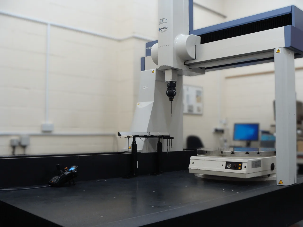
An articulated arm coordinate measuring machine is a portable measuring instrument built as a serial chain of precision rotary joints, six or seven axes in total, each carrying an angular encoder, terminated by a probe handle that the operator moves by hand around the workpiece. The arm computes stylus position by forward kinematics from the six or seven joint angles and the calibrated link lengths, converting hand motion into three dimensional coordinate data at the rate of a point per touch or hundreds of points per second in scanning mode. Reaching roughly 1.5 to 4.5 m from its base, it brings the measuring machine to the part instead of moving the part to a machine.
The arm earns its place in dimensional metrology wherever parts cannot travel: assembly fixtures on the shop floor, weldments too heavy for a granite table, machine tools measured in place, tubular structures, and first article inspection at suppliers without a quality lab. The purchase decision centers on four quantities: single point articulation and volumetric accuracy as defined by ISO 10360-12, scan volume, counterbalance ergonomics for the operator, and the thermal and mounting discipline that keeps a portable instrument honest. Buyers who treat those four explicitly get a machine that settles tolerance arguments; buyers who compare only reach and price get a device that argues with itself between morning and afternoon.
This page treats the articulated arm CMM as a specification object: how the serial kinematics produce and lose accuracy, what ISO 10360-12 verification actually measures, how 6 axis and 7 axis configurations and probe options divide the market, and what an RFQ must state about accuracy class, mounting, environment, and software so that the arm that arrives is the arm that was promised. It is written for engineers who measure parts with their hands on the tool.
Chapter 1 / 06
What an Articulated Arm CMM Is and What Is Being Decided
Mechanically the arm is a chain: a base with magnetic or threaded mounting, two or three long carbon or aluminum links, rotary joints with encoders reading to roughly 1 arc second class, and a wrist cluster of two or three further joints carrying the handle and probe. A six axis arm has six encoders; a seven axis arm inserts an additional rotary joint at the base or mid arm, which removes the classic dead spots where the wrist aligns and the arm loses orientation freedom. The controller fuses the joint angles into tool center point coordinates hundreds of times per second. Because every joint angle error multiplies through the kinematic chain by its distance from the probe, arm accuracy is stated as a spatial quantity over a sphere, not as a per axis scale error.
What is being decided at purchase is the division of labor between this arm and everything else in the metrology cabinet. The arm trades the micro level accuracy of a bridge CMM for portability and reach: a good 2 m class arm verifies single point positions to roughly 0.025 to 0.10 mm and scans surfaces at roughly 0.035 to 0.15 mm class depending on grade, where a bridge machine holds a few micrometers on small volumes. Against the laser tracker the arm trades long range for single operator convenience: a tracker needs two people or a motorized reflector for many tasks and beats the arm beyond about 6 m. The arm owns the middle: bench to truck sized objects, measured by one operator, in minutes, with software the plant already runs.
The decision is also organizational. An arm lives or dies by operator technique because the human is the machine axis: probe force, arm posture, and temperature handling all enter the result. Plants that assign one or two trained owners to the arm, keep its verification records, and manage its stylus sets get results that stand in supplier disputes. Plants that store it in the tool crib next to the calipers and lend it to whoever needs it get scatter that discredits the instrument. The RFQ should therefore include training days and a written operating procedure as line items, not accessories.
Within the product landscape the arm sits beside three cousins that buyers frequently conflate. The bridge CMM is the accuracy authority at small volume, and every arm program should be cross checked against it on gauge correlation parts. The gantry class carries the arm's portability ceiling upward in volume but not in travel; a part that stays in its machine tool is arm territory. And the structured light and industrial camera scanner packages overlap the arm's scanning role with faster full field capture but weaker edge and hole metrology; many arms accept exactly those scanner heads as attachments, which is why the probe interface line in the specification matters more than it first appears.
Finally, what is being decided is where the truth of the measurement will live. A portable arm measures in the part frame through datum alignment: the operator measures datum features, software constructs the coordinate system, and everything else is reported in that frame. Tolerances that reference datums the arm cannot physically capture, because they were machined away or live on another component, cannot be verified by any arm regardless of accuracy class. Deciding datum accessibility before purchase is a five minute exercise on the drawing that prevents the most common post purchase disappointment in portable metrology.
Chapter 2 / 06
How the Arm Produces and Holds Accuracy
The governing standard for this class is ISO 10360-12, which defines acceptance and reverification tests for articulated arm coordinate measuring machines. Its headline quantities are single point articulation error, the scatter of points measured at the same location from many different arm postures, which exposes joint eccentricity and counterbalance slop; and volumetric length measuring error over gauge lengths measured inside the working volume, commonly with a ball bar or step gauge tracked in multiple orientations. Datasheets quote these as MPE bands; a current 1.5 to 2 m industrial arm quotes single point articulation around 0.025 to 0.060 mm and length error around 0.020 to 0.070 mm depending on grade, while large 3.5 to 4.5 m arms range roughly 0.075 to 0.250 mm.
Error propagation is inherently geometric. An encoder reading error of one arc second at a 1 m link radius is about 5 um at that joint alone; six joints in series with geometry errors, bearing play, and thermal growth of the carbon tubes stack into the tens of micrometers even on a healthy arm. This is why arm verification is statistical: the same point probed from many postures scatters around truth by an amount that reflects posture diversity, and the ISO test fixes the posture set so the number is comparable between vendors. It is also why an arm knocked against a fixture drifts: one bent link or shifted encoder zero displaces every downstream computation. Post collision verification is not bureaucracy; it is the only way to know the arm still meets its band.
Thermal behavior is the portable instrument's particular weakness. The arm is carried between a 20 deg C calibration room and a 28 deg C shop, or from a car boot in winter to a welding bay; carbon fiber tubes attenuate axial growth but joints and housings are aluminum and steel. Vendors compensate with material models and internal temperature sensors, and the accuracy statement carries an operating window, commonly 10 to 40 deg C with limits on gradients. The practical discipline is soak time: let the arm sit at the part for 15 to 30 minutes before measuring, verify with a quick ball bar check when the environment is suspect, and avoid measuring across a sunlight patch that heats one link. Plants that chart the arm's daily check artifact see thermal effects as a predictable band rather than a mystery.
Mounting stiffness sets the lower bound of everything. The arm base bolts to a magnetic plate on a machine tool table, a threaded insert in a granite cart, or a tripod on a shop floor; every micron of base motion adds directly to every point. Tripod measurements of tight tolerances fail on concrete expansion joints, forklift traffic, and wooden mezzanines. The verification discipline extends to the mount: a quick two station self check, where the same artifact is measured from two base positions, exposes base movement and arm drift in ten minutes and belongs in the daily routine for critical work.
Probing systems carry their own error budgets into the chain. A touch trigger probe on the arm registers discrete points with the same pretravel physics as on a CMM, qualified on a reference sphere in the handle cradle; a scanning probe streams points continuously while the operator sweeps the stylus across the surface, and its error band includes operator sweep speed. Laser line scanner heads mounted in place of the tactile probe add sensor error, standoff sensitivity, and surface reflectivity effects, verified against a calibrated ball or plane artifact. On arms the stated system accuracy must be read as arm plus sensor: a scanner head specified at 0.020 mm on a rigid carrier does not make a 0.080 mm arm a 0.020 mm system. Vendors publish combined figures; RFQs should demand the combined figure for every proposed configuration, per ISO 10360-12 for tactile and its annex practice for scanning.
Software closes the loop from points to decisions. Arm packages construct geometry, align datums, evaluate GD&T per the same standards family as fixed machines, and export to quality systems. Two software behaviors matter for accuracy honesty in practice: probe compensation, the stylus tip radius correction applied from the qualification data, and alignment method, because a best fit alignment across form errors hides datum logic while a datum simulator alignment follows the drawing. Training that covers these two topics is worth more per hour than any hardware option, a statement every arm owner eventually writes in the margin of their procedure.
Chapter 3 / 06
Types, Construction, and Duty Boundaries
The market divides first by axis count. Six axis arms cover most duties and cost less; they lose orientation freedom in wrist aligned postures, which experienced operators route around. Seven axis arms add an infinite rotation joint that eliminates dead spots, allow the operator to keep a neutral wrist through long scan sweeps, and dominate scanning heavy applications; the extra joint adds cost and one more encoder to calibrate. Within both counts, size grades run from 1.5 m reach bench arms through 2.5 to 3.0 m general purpose arms to 4 to 4.5 m large part arms, with accuracy degrading roughly with reach.
Construction grades track the intended floor. Lab grade arms ride in cases between climate rooms and carry the tightest bands; industrial arms add sealed joints, temperature compensation ranges, and counterbalance systems rated for continuous shop use; intrinsically safe versions serve explosive atmospheres in plants that need them. Counterbalance deserves attention in the RFQ: spring or pneumatic systems that make a 9 to 11 kg arm manageable through a shift differ measurably in fatigue, and the arm that is exhausting to hold gets swept too fast and scanned too sloppily to hold its band.
Probe outfits define capability. The baseline handle accepts touch trigger probes for point measurement, the workhorse of fixture and machine tool checks. Scan probes add continuous surface capture for form and contour at arm class accuracy. Laser scanner heads turn the arm into a swept surface digitizer for sheet metal, castings, and reverse engineering, with point clouds into the millions and uncertainty tens of micrometers at best. Integrated machine mount kits let the arm index on a machine tool table for in place checks of spindles and tables; long stylus and extension sets reach deep bores at the cost of a wider error band that qualification partially recovers.
Duty boundaries are sharp and worth writing on the case lid. The arm does not replace a gauge block or micrometer routine for sub 0.01 mm dimensions; hand tools and the fixed CMM keep that domain. It does not replace the surface roughness tester for texture, the optical comparator for small profile shadows, or the vision measuring machine for small electronics geometry; each of those instruments resolves features below the arm's stylus and band. It does not beat a laser tracker beyond several meters or on large volume densification where the tracker with a scanner or a photogrammetry bundle wins on speed. Its territory is the 0.1 m to 4 m object with tolerances from roughly 0.05 mm upward, measured where it stands.
Environmental boundaries mirror the thermal discussion: direct sun, radiating furnaces, and doors opening onto winter air all exceed compensation models. Part temperature itself is a boundary: measuring a weldment straight off the weld table measures its hot shape, and the drawing tolerances apply at 20 deg C. Honest arm practice either waits for soak or applies documented part temperature correction, and the choice belongs in the measurement plan, not the operator's discretion.
The construction map below pairs common duties with the configuration that performs and the one that causes callbacks.
Duty
Suitable configuration
Configuration to avoid
Fixture and jig certification on the floor
2.5 to 3.0 m industrial 6 axis, trigger probe, magnetic base kit
Lab grade arm in an open fabrication bay
Machine tool geometry checks in place
2.5 m arm, machine mount kit, long stylus set
tripod on cracked slab for spindle alignment checks
Sheet metal and casting scan digitizing
7 axis arm with laser line head, combined accuracy quoted
Trigger probe programs where surfaces, not points, are the deliverable
Tubing and chassis weld verification
3.0 to 4.5 m arm, scan probe, two station self check routine
Single station measurement of long structures without base repositioning plan
First article at supplier without lab
2.0 to 2.5 m arm, gauge correlation set, fixed procedure
Arm shared informally among staff without training records
Sub 0.01 mm tolerance verification
Bridge CMM or hand metrology; not an arm duty
Any arm, regardless of datasheet optimism
Chapter 4 / 06
Key Specification Parameters
The decode table lists the parameters that decide whether a quoted arm matches the work. Every row is a line the RFQ should force into writing; commentary follows on the rows where quotations most often blur.
Attribute
Typical range or options
What it decides
Axes
6 axis or 7 axis
Posture freedom, scan sweep ergonomics, and price class
Measuring reach
1.5 to 4.5 m sphere radius
Part envelope from one or few base positions
Single point articulation MPE
0.025 mm bench arms to 0.250 mm large arms
Position tolerance arbitration limit
Volumetric length error MPE
0.020 to 0.290 mm by size and grade
Distance and feature to feature capability
Scan system accuracy
0.035 to 0.150 mm combined arm plus scanner
Surface and contour work credibility
Probe interface
Trigger, scan probe, laser line head, extensions
Feature coverage over the arm's life
Counterbalance and mass
8 to 12 kg typical; pneumatic or spring balance
Operator endurance and therefore data quality
Thermal compensation range
10 to 40 deg C typical window
Shop floor honesty of the accuracy statement
Mounting options
Magnetic plate, threaded cart, machine mount, tripod
Stiffness floor under every measurement
Software and outputs
GD&T evaluation, CAD import, quality system export
From points to accepted or rejected parts
The two MPE lines are the contract. They must be quoted per ISO 10360-12 with the test description, gauge lengths, and posture count, and the acceptance test in the purchase contract should repeat them on delivery with your artifact if possible. Vendors also publish a volumetric "space within which" figure for scan heads; demand the combined arm plus head band for the exact configuration quoted, because mixing the head's standalone figure with the arm's figure understates the system error in every case.
Reach interacts with accuracy in a way the datasheet front page hides: the MPE band already assumes full reach use, but practical measurement quality improves when the arm works inside 70 to 80 percent of reach with good posture diversity. A 1.5 m arm measuring a 2.8 m part from two base positions usually beats a 3.0 m arm stretching from one, at the cost of setup time. The RFQ should state the largest typical part and ask for the vendor's recommended base plan; the answer separates vendors who understand the shop from vendors who read the same catalog.
Probe interface future proofs the purchase. Arms procured for trigger work grow into scanning within two years in most plants; an arm whose handle accepts the vendor's scanner heads and scan probes without factory return protects that path. Extension styli widen reach inside bores at a stated band penalty; the quotation should carry the penalty numbers for the stylus set offered, per length class, rather than a single stylus figure.
Budget planning across the classes; ranges in USD for arm plus one tactile probe, excluding scanner heads, cases beyond standard, and software options beyond base GD&T.
Class
Reach and axes
Budget range USD
Bench grade, tight band
1.5 m, 6 axis
25,000 to 45,000
General industrial
2.0 to 2.5 m, 6 axis
35,000 to 65,000
Scanning oriented
2.5 to 3.0 m, 7 axis
55,000 to 95,000
Large part industrial
3.5 to 4.5 m, 7 axis
90,000 to 160,000
Laser line scanner head add on
per head
15,000 to 45,000
Annual calibration and verification service
per year
2,000 to 6,000
Chapter 5 / 06
Selection Decision Factors and RFQ Language
The decision list below compresses the page into the order a team should walk it, and each step writes a line of the RFQ.
State the true part set: envelopes, weights, whether they travel to a bench or must be measured in place, and the datum features each drawing references.
State the tolerance families: the tightest position, distance, and surface tolerances the arm must arbitrate; select a grade whose single point and length MPE sit at or below one third of the tightest value.
Choose axis count by ergonomics and scan duty: 6 axis for point work and budgets, 7 axis when scanning sweeps and posture freedom drive throughput.
Choose reach from the base plan: part size versus accuracy inside 70 to 80 percent of reach; prefer two station plans on large parts over maximum reach stretching.
Fix the probe set now and the scanner path later: trigger baseline, scan probe where form is routine, scanner head where digitizing is routine; demand combined accuracy bands per configuration.
Audit the environment: temperature swings, sunlight, floor condition, and mounting surfaces; write the soak and daily artifact check routine into the operating procedure.
Demand ISO 10360-12 acceptance on delivery and an annual reverification plan with the same tests; attach the training days and the collision and recalibration policy.
Compare software on your parts: ask for a demonstration measurement of one of your drawings on your data, evaluating datums and GD&T exactly as your quality system will report them.
The comparison that usually survives to the final round is between a mid size 6 axis and a 7 axis of the same grade, and the table below frames it honestly.
Attribute
6 axis industrial arm
7 axis industrial arm
Dead postures near wrist alignment
present, routed by technique
eliminated by infinite joint
Scan sweep endurance
operator compensates with steps
neutral wrist through the sweep
Single point MPE, 2.5 m class
about 0.045 to 0.060 mm
about 0.040 to 0.055 mm
Mass and balance hardware
8 to 10 kg typical
9 to 12 kg typical
Price step
baseline
about 20 to 40 percent above
Best fit duty
points, fixtures, machine checks
scanning, long programs, digitizing
The RFQ block for an articulated arm should read: quantity; axis count; reach; ISO 10360-12 single point and length MPE with test description; scan probe and scanner head options with combined bands; stylus set with per extension penalties; counterbalance specification; thermal compensation window; mounting kit list including magnetic plate and machine mount; software modules with GD&T standard references and export formats; training days on site; acceptance test protocol on delivery and annual reverification terms; collision and recalibration policy with turnaround; and case, cradle, and accessory list. A quotation missing the combined scanner band or the acceptance retest terms is incomplete at any price.
Chapter 6 / 06
Field Practice, Standards, Failure Modes, and Maintenance
Daily practice decides whether the arm performs to its band. The routine that professional shops run takes fifteen minutes: mount the base on the stiffest surface available; qualify the probe on its reference sphere; measure the daily check artifact, a certified ball bar or a machined step gauge kept beside the arm; log the result on a control chart; then measure parts. When the chart drifts, the cause is almost always one of four: thermal soak skipped, base moved, stylus changed without requalification, or the arm took a knock. Ten minutes of diagnosis saves a day of argument with a supplier over parts that were fine.
Operating technique enters the error budget in three documented ways. Probe force: trigger probes on arms are handheld, so the operator controls approach speed and force; consistent, light, axial triggering is the training goal. Posture diversity: measuring the same feature from similar arm postures repeats systematic errors instead of averaging them; good practice captures critical features from at least two distinct postures. Sweep discipline in scanning: speed and stylus angle within the vendor window, typically stated as maximum mm per second and inclination range, keep the scanner inside its band; the temptation to sweep faster at the end of a shift is the last hour's data quality quietly degrading.
The standards stack for arms is compact. ISO 10360-12 governs acceptance and reverification with the single point articulation and length error tests cited throughout this page; the neighboring parts of ISO 10360 cover the probes and scanning systems arms carry. ISO 14253 supplies the decision rules for conformity with uncertainty, the document that resolves whether a 0.062 reading against a 0.060 band on a 0.050 MPE instrument is a reject; the arm's band forces this discipline more often than any fixed machine. Where national laboratory method notes exist, such as the NIST technical note on CMM performance assessment referenced below, they inform witness test practice even though written around fixed machines.
Failure modes fall into five families in field experience. Collision damage, the leading cause of out of band arms: a dropped or knocked arm bends a link or shifts an encoder zero; the remedy is immediate verification and factory recalibration, never quiet hope. Thermal abuse: storage in a hot van followed by immediate use; the remedy is soak discipline and the daily chart. Mounting complacency: tripods on unsuitable floors; the remedy is the stiff mount rule and two station checks. Stylus management: bent or dirty styli and missed requalification; the remedy is a stylus log and qualification at every change. Software datum drift: programs edited informally until the alignment no longer matches the drawing; the remedy is locked program versions under the quality system, identical to any CMM.
Maintenance intervals are short and cheap. Every use: joint and handle cleanliness, stylus check. Monthly: encoder housing inspection, cable and connector check, case interior clean. Annually: ISO 10360-12 reverification by vendor or accredited lab, probe and scanner recalibration, firmware and software maintenance, and review of the control charts for drift signatures. Every two to three years: factory or full service recalibration including counterbalance adjustment, joint preload checks, and recalibration of the kinematic parameters. Budget the annual verification at 2,000 to 6,000 USD and treat the two to three year recalibration as a planned line, because the alternative is discovering it through a failed part dispute.
The organizational wrapper remains the strongest maintenance tool: named owners, training records, the control chart culture, a written procedure for mounting, soak, qualification, and two station checks, and a standing relationship with the vendor's service bench. An arm managed this way holds a decade of service and quietly becomes the plant's most trusted arbitrator for everything too big to move and too valuable to guess about.
FAQ
What accuracy should I expect from an articulated arm CMM?
Expect ISO 10360-12 single point articulation errors of roughly 0.025 to 0.060 mm on 1.5 to 2.5 m arms and 0.075 to 0.250 mm on 3.5 to 4.5 m arms, with volumetric length errors in similar bands. Scanner heads add error; the honest figure is the combined arm plus head band, commonly 0.035 to 0.150 mm. Treat the arm as the tool for tolerances from about 0.05 mm upward, and cross check tighter cases against a fixed CMM.
Should I buy a 6 axis or a 7 axis arm?
Buy 6 axis for point driven work such as fixture checks and machine tool geometry at lower cost. Buy 7 axis when scanning dominates: the extra infinite joint removes wrist aligned dead postures and lets the operator hold a neutral wrist through long sweeps, which shows up directly in scan quality and operator endurance. The price step is typically 20 to 40 percent, and scanning heavy plants rarely regret paying it.
How do I keep a portable arm accurate on the shop floor?
Mount on the stiffest surface available, soak the arm at the part for 15 to 30 minutes across temperature changes, qualify the probe after every stylus change, and run a daily ball bar or artifact check logged on a control chart. Add a two station self check for critical measurements. These habits keep results inside the vendor band; skipping them is the usual cause of drift complaints.
Can an arm replace our bridge CMM?
No, and the best plants use both deliberately. The bridge machine holds a few micrometers over small volumes and remains the authority for tight tolerances and gauge correlation. The arm covers parts too large or too fixed to travel, at bands ten to fifty times wider, with one operator and minutes of setup. Cross correlate on shared parts so the arm's results carry the fixed machine's credibility.
What does ISO 10360-12 actually test?
It defines acceptance and reverification tests specific to arms: single point articulation error, where one point is measured from many arm postures to expose posture dependent scatter, and volumetric length measuring error, where calibrated gauge lengths such as ball bars are measured inside the volume in defined orientations. Datasheet MPE figures for arms should cite this standard; numbers quoted without a test description are not comparable between vendors.
Is a laser scanner head on the arm worth adding?
Yes when your work includes freeform surfaces, castings, sheet metal, or reverse engineering; the head captures millions of points far faster than tactile scanning, at combined bands typically between 0.035 and 0.150 mm. It does not sharpen the arm's accuracy, and edges, small holes, and datum features still belong to the tactile probe. Specify the combined arm plus head accuracy band in the RFQ before comparing prices.
What maintenance does an arm need, and how often?
Daily: probe qualification and a check artifact measurement. Monthly: joints, cables, and connectors inspected, case cleaned. Annually: ISO 10360-12 reverification and sensor recalibration, budget roughly 2,000 to 6,000 USD. Every two to three years: full service recalibration including counterbalance and kinematic parameters. After any collision: immediate verification before further use, and factory recalibration if the band moved.