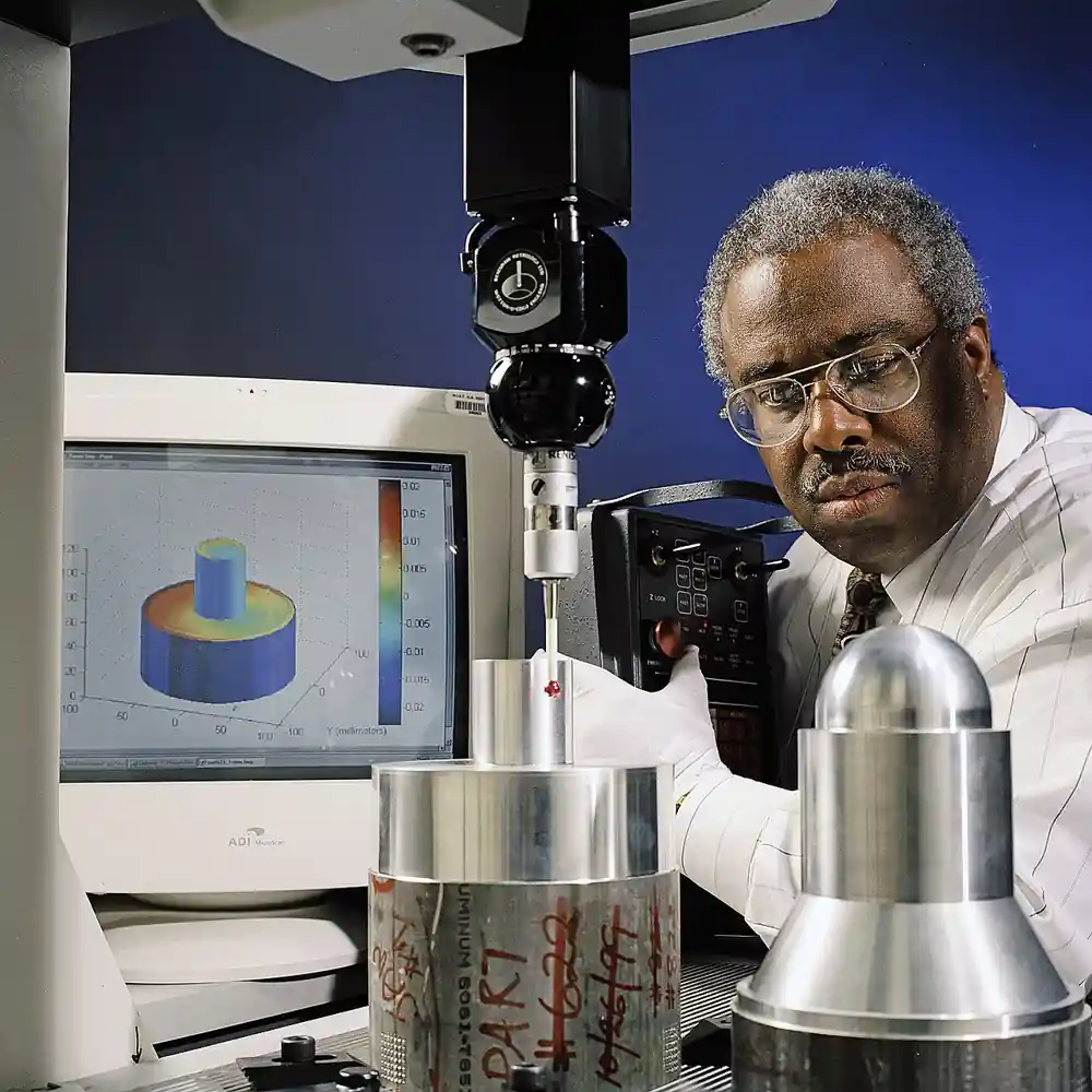
A bridge CMM is a coordinate measuring machine built as a moving bridge that rides on two legs along a fixed granite table, carrying a spindle and probe that record point positions in X, Y, and Z. It is the most common CMM structure in machine shops and inspection labs, offered in X travels from about 500 to 1600 mm, and it is the default instrument for verifying machined parts against GD&T callouts, first article requirements, and customer drawings. This page decodes the specification sheet: accuracy classes per ISO 10360-2, probe system choices, construction and thermal limits, and the cost lines buyers routinely miss.
The buying decision is rarely brand first. It is size class, then accuracy class, then probe strategy, then environment, because each choice narrows the next. A machine sized for a 900 mm travel envelope but installed in a room that swings 4 deg C across a shift will not hold its catalog number, and a scanning probe bought without programming resources will sit unused. The chapters below follow that decision order so a specifier can move from part list to RFQ with numbers attached to every line.
A bridge CMM is the tool of record for 3D dimensional inspection of machined parts: sub-micron scales, air bearing axes, and probe systems that deliver either one verified point per touch or hundreds of points per second. This reference explains the moving bridge layout, what the ISO 10360-2 accuracy formula actually promises, how touch-trigger and scanning probes divide the work, and what to specify, install, and maintain so the machine holds its catalog accuracy in daily production.
Chapter 1 / 06
What is a Bridge CMM
Definition and structure
A bridge CMM is a coordinate measuring machine whose moving element is a bridge: two legs that straddle a fixed granite table and travel along its length in Y, a carriage that traverses the crossbeam in X, and a vertical spindle that carries the probe in Z. The part does not move during measurement. All three axes carry scale feedback; at the instant the probe touches the part, the controller latches the three scale readings and hands one calibrated point to the software. Thousands of such points become features: bore diameters, axial lengths, hole pattern positions, angles between faces, and form profiles compared against the CAD model or the drawing.
The bridge layout dominates general purpose dimensional metrology because it wraps stiff, error compensated axes around a dense, well damped table at a price a machining business can justify. Catalog X travels cluster at 500, 700, 900, 1200, and 1600 mm, with Y typically 20 to 50 percent deeper than X and Z ranging from 400 to 1500 mm depending on class. The granite table both carries the part and defines the reference geometry the axes ride on, which is why table flatness, floor quality, and thermal stability show up directly in the error budget rather than as abstract catalog terms.
What it measures, and what it does not
Dimension: diameters of bores and shafts, widths of grooves, depths of pockets, distances between features. Position: true position of bolt patterns to a datum frame, coaxiality between bores, angle between machined faces. Form: flatness of gasket faces, circularity and cylindricity of bearing journals, and surface profile against CAD when a scanning probe is fitted. All of it is traceable geometry, reported with uncertainty statements a customer auditor can follow.
A bridge CMM does not measure everything. Surface texture belongs to a surface roughness tester, whose diamond stylus and defined cutoff wavelengths resolve Ra and Rz values a 3 mm probe ball mechanically filters out. Very dense freeform capture for reverse engineering is faster with optical methods. And a CMM report is only as good as its last calibration, which is why the later chapters treat verification and interim checks as part of the product, not an afterthought.
Where the bridge sits among the alternatives
The bridge is the middle of the measuring machine family, and most shops never need to leave it. Gantry style machines stretch the same Cartesian concept past roughly 3 m of travel for molds, airframe sections, and vehicle structures. Horizontal arm machines trade some accuracy for wide, shallow volumes suited to body panels and sheet metal. Portable arms and trackers carry the instrument to the part on the shop floor. At the bench end, a height gauge and a dial indicator on a granite surface plate still close out simple single dimension checks, an optical comparator screens 2D contour profiles against a magnified chart, and a laser distance meter handles long layout distances at millimeter level accuracy. The bridge CMM earns its floor space when parts carry several 3D callouts tighter than about 0.1 mm and volumes justify program driven repeat measurement.
The decision you are actually making
Specifying a bridge CMM means deciding four things in order: size class (travel envelope and table load), accuracy class (the ISO 10360-2 formula band), probe strategy (touch-trigger, analog scanning, or both with a change rack), and environment (lab room versus a shop floor rated machine). Each decision constrains the next: size class fixes the granite mass, room dimensions, and foundation; accuracy class narrows the building choices; probe strategy sets the controller and software requirements; and environment decides whether you build a 20 deg C room or buy a compensated machine and accept a looser accuracy statement. The rest of this page follows that order.
Chapter 2 / 06
Working Principle and Probe Types
Cartesian probing in three axes
The machine knows where its probe tip is at all times from three scale readings plus a stored map of its own geometric errors. A bridge CMM is not a perfect Cartesian instrument: axis squareness, straightness, roll, pitch, and yaw contribute roughly 21 separable geometric error terms. Manufacturers measure these at final assembly and store a compensation map in the controller, which corrects each raw scale reading before it reaches the software. When you read a datasheet, this is why length error grows with distance: the residual, uncompensated geometry plus scale error is quoted as the E0 formula, verified per ISO 10360-2 with calibrated artifacts.
At contact, the software subtracts the stylus ball radius vector to find the touched surface point, so stylus qualification accuracy propagates into every dimension. Points are then fitted into geometry: least squares (Gaussian) fitting is the default for size because it averages probing scatter, while minimum zone fitting is used when reporting form per the drawing callout. A diameter measured from 8 points and from 64 points on the same bore can differ by a micrometer or more if the bore has form error, so programs fix point counts and locations to keep results comparable run over run.
Touch-trigger probing
A touch-trigger probe holds a stylus on a kinematic seat. When the ball touches the part, the seat unseats by a few micrometers, a reed switch or optical sensor fires, and the controller latches the axis positions with a small, repeatable pretravel correction applied. The method delivers one point per touch, and in practice machine motion limits acquisition to a few points per second. Trigger force at the ball runs about 0.03 to 0.3 N depending on probe model and stylus length, and trigger repeatability on quality probes is on the order of 0.3 to 0.5 um at the ball, before stylus bending effects.
Touch-trigger is the right tool for size and position: diameters with 4 to 16 points per circle, hole patterns, plane to plane distances, and quick stock checks. Motorized indexable heads rotate the probe in repeatable angle steps (7.5 degree increments are typical) so one stylus reaches five sides of a part without operator intervention. Where it struggles is form: a 32 point circularity check misses lobing and chatter that 800 points would expose, and each touch costs seconds of machine time.
Analog scanning probing
An analog scanning probe holds the stylus at a small, constant deflection while the machine drags the ball along the surface. The deflection signal is measured continuously, so the controller records a stream of points: several hundred to more than 1000 points per second on standard systems, at maintained forces of 0.05 to 0.2 N. A full 360 degree circularity scan on a 25 mm bore completes in a few seconds instead of the minute a 30 touch strategy needs, and profile tolerance zones against CAD only become practical with this data density.
Scanning demands more than a probe swap. It requires CNC axis control with smooth velocity blending, a stiffer dynamic loop, thermally stable structure, and software that filters thousands of points into stable features without inventing geometry. Scanning probing performance is verified separately from length error, under the scanning measurement test clauses of the ISO 10360 series, so a datasheet that quotes E0 alone tells you nothing about scan quality on form features. Check both numbers against your tightest form callout.
Styli, heads, and qualification
The stylus is a precision consumable. Balls are synthetic ruby (aluminum oxide) for wear resistance, from 0.3 mm for small bores up to 8 mm for deep features; shafts are tungsten carbide or ceramic, chosen for stiffness at length; star configurations sweep sides of features; extension bars reach deep pockets at the cost of bending under trigger force. Every stylus change, and every head angle change on indexed heads, requires qualification against a reference sphere of known diameter: a 2 to 5 minute routine that teaches the controller the effective ball center offset. Skipping or rushing it is one of the most common sources of unexplained micrometer level shifts between operators and shifts.
Alignment: 3-2-1 to CAD best fit
Before any feature is measured, the part coordinate system must be built. The classical 3-2-1 alignment takes three points on a primary plane, two on a secondary axis, and one for the origin: six points, a few seconds, and every later result depends on them. Datum based alignment follows the drawing datum frame, which is what GD&T reporting requires. CAD best fit (least squares over a cloud of probed points) suits castings and organic surfaces where no usable machined datum exists; iterated versions refine the fit until movement falls below a set threshold, typically 0.001 mm class. Alignment error does not average out; it biases the entire report, so the RFQ should state which datum scheme each part family uses.
When non-contact methods belong in the plan
Contact probing needs to reach the feature with a ball, which fails on soft, thin, or very small geometry. A vision measuring machine with telecentric optics measures 2D features on small or delicate parts at sub-micron scale repeatability, and an industrial camera in a machine vision cell screens presence, position, and 2D dimensions inline at production speed. A structured light 3D scanner captures millions of points across a whole surface in minutes for reverse engineering and first pass comparison, though its per point accuracy on reflective metal runs tens of micrometers against the 1 to 3 um a bridge CMM delivers on discrete features. For roundness critical work such as bearing raceways, a dedicated roundness tester with an air bearing spindle reaches radial accuracy a bridge machine cannot match. None of these replaces the bridge CMM for traceable 3D GD&T verification; they complement it, and Chapter 5 helps you decide which instruments the workload actually requires.
Chapter 3 / 06
Construction, Materials, and Accuracy Grades
Granite, structure, and mass
The table is aged natural granite, ground to flatness measured in single micrometers across the working width, and it does three jobs: reference surface for the Y axis air bearings, part carrier, and thermal ballast. Table masses run from roughly 300 kg on a compact machine to several tonnes on a 1600 mm class bridge, and that mass is deliberate: it damps vibration, slows temperature change, and keeps the reference geometry stable through daily room cycling. Rated part loads span about 150 kg on compact tables to 1000 kg and beyond on large granite, fixture weight included.
The moving bridge is a stiffness to weight compromise. Aluminum extrusion beams keep the mass low for fast CNC service, at the price of a thermal expansion coefficient near 23 um per meter per deg C. Ceramic and silicon carbide beams cut that to roughly 4 um per meter per deg C and add stiffness, which is why they appear on lab class machines where the beam temperature gradient itself is an error term. Steel sits between the two at about 11.5 um per meter per deg C and wins on cost for mid range builds.
Air bearings, drives, and air supply
All sliding interfaces run on preloaded air bearings: no rolling elements, no wear, and an air film only a few micrometers thick averaging out residual guide error. The machine consumes clean, dry compressed air continuously: 5.5 to 7.0 bar at the inlet, 50 to 150 L/min depending on size, filtered to at least 40 um with coalescing and drying stages ahead of it. Oil or water in the supply is a silent killer: it contaminates bearing surfaces and shifts axis friction, which shows up as mid program reversibility errors long before anything looks wrong on the pressure gauge.
Entry and mid machines use toothed belt or recirculating ball screw drives with DC or AC servo motors; performance machines move to direct drive linear motors for acceleration and smooth low speed scanning. Catalog drive numbers to compare: maximum positioning speed, typically 300 to 500 mm/s on CNC models, and the programmable measuring speed range, typically a fraction of that in contact. Higher speed shortens cycle time only on point rich programs; on sparse touch-trigger work the difference between machine models is minor next to program structure.
Scales and feedback
Each axis closes its position loop on a glass linear encoder: a fine graduated scale read optically and interpolated electronically to 0.05 to 0.1 um resolution on current machines. Higher accuracy machines use low expansion ceramic glass scale substrates so scale temperature error stays small even when the room drifts, and the residual scale error is one of the terms folded into the quoted E0 formula. Scale health is a calibration matter, not a maintenance item: crash shock can shift a scale mounting and that shift appears as a step change in interim check results.
Thermal behavior is the accuracy story
Dimensional metrology is defined at 20 deg C: ISO 1 sets the standard reference temperature for geometric specification, and every catalog accuracy statement assumes it. A lab class installation holds 19 to 21 deg C with spatial gradients held to about 0.5 to 1.0 deg C through the measuring volume, 30 to 60 percent relative humidity, and parts soaked until they match the room. The gradient number matters as much as the band: a machine standing in a 0.3 deg C per meter vertical gradient is permanently bent relative to its calibration state, and a 1000 mm aluminum beam flexing 23 um per deg C does not need much gradient to lose a micrometer class budget.
Every machine above entry level ships with temperature compensation: sensors on the scales and structure, and often a part material master (steel, aluminum, cast iron coefficients) applied in software. Compensation works well inside its calibrated envelope and degrades outside it, which is the real meaning of the operating temperature range line in the datasheet.
Accuracy grades and the MPE formula
ISO 10360-2 expresses length error as a maximum permissible error formula: E0 = A + L/K um, where L is measured length in mm. Production class bridges quote around 2.5 + L/300 um. Precision classes around 1.7 + L/333 um. Lab class machines reach 0.5 + L/500 um and better. Evaluated at 500 mm those formulas give about 4.2, 3.2, and 1.5 um; evaluated at 1600 mm they give about 7.8, 6.5, and 3.7 um. The formula slope is what you are paying for when you step up a class: better scales, ceramic structure, tighter compensation, and longer factory verification. Probing error is quoted and verified separately from E0, so a full accuracy statement always has at least two numbers.
Duty boundaries: lab machine or shop floor machine
Lab class machines specify roughly 18 to 22 deg C, low gradients, and clean air, and they deliver their best formula only inside that discipline. Shop floor rated bridges carry protected ways, sealed scales, and wider compensation tables to run in roughly 15 to 40 deg C environments with temperature swings, at a stated accuracy typically 1.5 to 2.5 times looser than the same size lab machine. The honest boundary test is environmental, not mechanical: if the inspection point cannot guarantee gradient control and part soak, buy the shop floor rating and write its looser E0 into the capability study. Near maximum table load, derate accuracy claims by about 20 percent, because granite deflection under load is not fully inside the factory error map.
Chapter 4 / 06
Key Specification Parameters
A bridge CMM datasheet is short, and every line interacts with the others. The table below lists the parameters that decide fit, in the order a specifier should read them, with the catalog spread you will see across mainstream vendors and the selection consequence of each line. Three more tables then separate the probe decision, the size class decision, and the cost picture.
Parameter
Typical catalog range
Why it matters in selection
X x Y x Z measuring travel
500 x 600 x 400 mm up to 1600 x 2400 x 1500 mm
Fixes the largest part envelope; fixture height, stylus reach, and head clearance must fit inside with room to spare
Length error MPE E0 (ISO 10360-2)
2.5 + L/300 um (production) down to 0.5 + L/500 um (lab class)
The headline accuracy; evaluate the formula at your longest measured length, not at 100 mm
Single stylus probing error
0.8 to 3.0 um form on a calibrated sphere
Governs results on small features: bore circularity, short plane flatness, thin wall position
Repeatability (typical)
0.5 to 2.0 um spread, run over run
Sets guard bands for SPC decisions and the limits you can trust on interim checks
Maximum part load
150 kg (compact) to 2000 kg (large granite)
Includes fixture weight; running near the limit shifts the error map, so plan 20 percent margin
Scanning data rate
200 to 1000+ points per second
Sets point density and cycle time on form and profile features; useless without filtering and stable dynamics
Probe change rack positions
4 to 12
Enables unattended runs that mix star styli, extensions, and angle heads in one program
Operating temperature range
16 to 26 deg C lab class; 15 to 40 deg C shop floor rated
This is the compensation envelope, not a comfort spec; outside it the correction model extrapolates
Air supply requirement
5.5 to 7.0 bar, 50 to 150 L/min, dry air, 40 um filtered
Compressor, dryer, and filtration are real cost lines and a common commissioning delay
Reading the travel and load lines
Buy travel for the largest part you expect to measure over the next 5 years, not the largest you have today. Working rules: longest part dimension plus 100 to 150 mm of clearance for stylus approach and clamps; Z must cover tallest part plus fixture height plus stylus plus head body, and the head alone adds 100 to 200 mm above the tip. A star stylus sweeping a bore needs side clearance for its horizontal balls, which effectively consumes travel in X and Y beyond the feature itself. On load, remember the fixture: a 400 kg casting clamped in a 250 kg fixture on a 600 kg rated table is not a comfortable margin, and deflection under load is exactly when the error map stops matching reality.
Reading the accuracy lines
E0 is a formula, so the only number that matters is the formula evaluated at your longest critical dimension: a 1.7 + L/333 um machine is 3.2 um at 500 mm but 6.5 um at 1600 mm. Acceptance under ISO 10360-2 uses calibrated step gauges or gauge block stacks measured in defined positions and orientations, and the machine must not exceed the stated MPE anywhere in the tested set; ask every vendor for the verification protocol, the artifact traceability, and whether the demonstration will be witnessed. Pair E0 with the probing error figure for the stylus configuration you will actually run, because long extensions degrade probing error well before they touch the length error budget.
Repeatability and accuracy are different purchases. Repeatability drives your ability to separate process variation from measurement variation in SPC; accuracy drives whether you can certify a tolerance to a customer. A machine can repeat to 0.5 um while being wrong by 6 um, and that is fine for trend control but not for acceptance at the tolerance limit.
Probe strategy: the second table
The probe decision is worth a dedicated comparison because it moves both capex and cycle time more than most machine options. The trade lines below reflect mainstream vendor pricing for complete head and probe packages, stylus sets excluded.
Attribute
Touch-trigger probe
Analog scanning probe
Data capture
One point per touch, a few points per second
200 to 1000+ points per second, continuous
Best suited for
Size, distance, and true position checks
Form (circularity, cylindricity, profile) and dense surface mapping
Probing force at the ball
0.03 to 0.3 N per touch
0.05 to 0.2 N maintained deflection
Smallest practical ball
0.3 mm on slim styli
0.5 mm typical
Cycle example, 8 bore block
8 to 20 min
3 to 8 min
Typical package price
8,000 to 20,000 USD
20,000 to 60,000 USD
Programming and analysis load
Moderate, feature based
Higher, plus form filtering and point cloud handling skills
The usual resolution is both: a touch-trigger probe for datum and size features, a scanning probe for form, and a change rack so one CNC program uses each without an operator. Budget the scanning decision honestly; a scanning head with nobody trained to write form programs is depreciation, not capability.
Size class mapping: the third table
Size class
X x Y x Z travels
Typical parts
Room and services
Compact
500 x 600 x 400 mm
Fixture plates, die components, medical and electronic machined parts
2.5 x 3.5 m cell, bench services, standard shop air
Engine blocks, machine frames, large weldments and molds
6 x 8 m lab, isolated slab, crane or forklift access
Size class is the first decision because it cascades: a mid class machine needs a real room, a dedicated air preparation line, and an isolated pad before accuracy is even discussed. Match the class to part families you can name, not to the one oversized part that arrived last quarter; oversized one offs are usually cheaper at a contract inspection lab than a machine class bought for them.
Chapter 5 / 06
Selection Decision Factors
Work the decision in this order. Every step below feeds the RFQ checklist that closes the chapter, and skipping a step is how organizations end up with a machine that is accurate on paper and unusable in practice.
Fix the part envelope and weight. List every part family for the next 5 years: largest overall dimension, heaviest configuration including fixtures, and deepest internal feature. Apply the 100 to 150 mm clearance rule from Chapter 4 to set travels, then check the table load rating with 20 percent margin. If parts run longer than about 2.5 to 3 m, stop: that work belongs to a gantry machine or a laser tracker, not the biggest bridge in the catalog.
Derive the accuracy class from the tightest GD&T callout. Use a test uncertainty ratio of at least 1:5, preferably 1:10: a 0.05 mm total band tolerance needs measurement uncertainty near 10 um, which most production class machines clear; a 0.01 mm band needs 2 um class performance at your feature lengths, which pushes you up a grade. Evaluate each candidate E0 formula at your longest critical dimension, and write that evaluation into the RFQ so vendors answer at your lengths, not their best case.
Choose the probe strategy. Touch-trigger for size and position, scanning for form and profile, both plus a change rack for mixed work. Decide who programs: scanning without trained metrology staff produces expensive point clouds and slow cycles. This decision also sets the controller tier and software modules, so make it before comparing machine prices or the quotes will not be comparable.
Set the throughput target. Count parts per shift and features per part. A manual bridge suits tens of features per day and operator driven checks; a CNC bridge with a change rack and palletized fixtures runs repeat programs unattended and comfortably covers first article plus in process sampling on 40 to 80 parts per shift. If a queue exists today, buy the CNC tier one level above the calculation, because demand grows into available capacity.
Define the environment honestly. A lab class machine needs a 19 to 21 deg C room with controlled gradients, an isolated slab, and part soak time in the schedule. If that room is not going to exist, specify a shop floor rated machine and use its looser accuracy statement in capability studies; buying lab accuracy and operating it shop floor loose wastes the premium and produces unexplainable results.
Match software to the workload. Requirements that matter: GD&T evaluation per ASME Y14.5 or the ISO GPS series (ISO 1101 and companions), CAD import with best fit alignment (STEP AP242 at minimum, native formats if customers supply them), offline programming against the CAD model, and report templates your customers accept. Software maintenance runs 10 to 18 percent of license cost per year; include it from day one.
Price ownership, not the machine. Sum machine, probe package, software, installation, air preparation, and fixtures, then add annual calibration and service for the planned life. Over 5 years, the annual lines add roughly 25 to 45 percent on top of machine capex, and spares (styli, filter cartridges, one trigger module) add 1 to 2 percent per year.
Ownership cost picture
Cost line
Entry manual bridge
Mid CNC with scanning
Large CNC bridge
Machine capex
30,000 to 60,000 USD
90,000 to 180,000 USD
250,000 to 600,000 USD
Probe and head package
5,000 to 15,000 USD
25,000 to 60,000 USD
40,000 to 90,000 USD
Metrology software license
5,000 to 20,000 USD
15,000 to 40,000 USD
25,000 to 60,000 USD
Installation, foundation, air prep
8,000 to 20,000 USD
20,000 to 45,000 USD
40,000 to 90,000 USD
Fixtures and pallets (one time)
2,000 to 8,000 USD
8,000 to 25,000 USD
20,000 to 50,000 USD
Annual calibration (ISO 10360-2)
2,000 to 4,000 USD
3,000 to 6,000 USD
4,000 to 9,000 USD
Annual service contract
1,500 to 3,000 USD
4,000 to 9,000 USD
10,000 to 25,000 USD
Read the table by column and by row. By column, note that everything below machine capex adds 40 to 70 percent for a CNC installation, which is why budget approval against the machine quote alone always runs over. By row, note that the annual lines are the ones that continue past year five: calibration cadence and service response are contractual, so negotiate them into the original purchase, not after the first breakdown.
What to write in the RFQ
Worst case GD&T: the tightest tolerance value, the feature it applies to, its datum frame, and its length, for example true position 0.1 mm at MMC to A, B, C over a 240 mm bolt pattern.
A feature length list so each vendor states E0 evaluated at your lengths, plus the probing error for your intended stylus configuration.
Material masters you need in compensation: aluminum, steel, cast iron, and any composites with known coefficients.
Heaviest part and fixture weight, fixture concept, and whether palletized interchange is required.
CAD formats in and out: STEP AP242 as baseline, native formats (Creo, NX, CATIA, SolidWorks) if customers supply them, and drawing revision control practice.
Throughput target in parts per day and shift pattern, and which part families run first article versus in process cycles.
Environment statement: temperature band and gradient you will guarantee, floor vibration situation, and air supply availability with pressure and dew point.
Acceptance test scope: ISO 10360-2 E0 verification plus probing and scanning tests per the applicable ISO 10360 parts, witnessed, with artifact traceability stated.
Calibration interval, interim check procedure and artifact supplied, warranty terms, training days at commissioning, and spare styli and filters in the first shipment.
Vendors who answer every line of this list with numbers are comparable; vendors who answer with brochure language are not, whatever the price difference appears to be.
Chapter 6 / 06
Field Practice: Installation, Calibration, and Maintenance
Siting, foundation, and commissioning
Site the machine before it is bought, because retrofitting a room is more expensive than building one. The standard prescription: an isolated concrete slab 200 to 300 mm thick, separated from the surrounding shop floor by an expansion joint, positioned away from presses, forklift aisles, overhead doors, and any equipment with impact cycles. Manufacturers publish permissible vibration criteria for each model; treat them as site selection data, not fine print. Plan power conditioning for the controller, dedicated conduit for the air line, and clear crane or forklift access for the granite delivery, which on large machines arrives in multi tonne pieces.
Commissioning is more than unloading. After leveling and anchoring, the technician re-verifies the geometric error map on site, because transport shifts machines, then runs the acceptance test: ISO 10360-2 verification of E0 with calibrated step gauges or gauge block artifacts measured in defined positions and orientations, plus probing tests appropriate to the installed probe system. Witness it, keep the signed results, and treat them as the baseline for every interim check that follows.
Temperature discipline and part soak
Run the room at a 20 deg C setpoint inside a 19 to 21 deg C band, gradients held near 0.5 to 1.0 deg C through the volume, 30 to 60 percent relative humidity, logged continuously. Soak parts before measuring: a steel part 1 deg C off the room is wrong by about 11.5 um per meter of dimension, and aluminum about 23 um per meter, no matter how good the machine is. Practical soak planning allows 2 to 8 h for typical machined parts and overnight for solid castings and weldments. Label incoming parts with soak start time and enforce it; most mystery measurement failures on new installations trace to warm parts, not machine faults.
Warm-up, stylus qualification, and interim checks
Daily start sequence: power on and let the controller stabilize 15 to 30 min, drive all axes through full travel to equalize bearings and scales, qualify styli on the reference sphere after any stylus or head change, then run a daily artifact check: measure a master part, a calibrated ball bar, or a reference sphere and log the result against control limits. A working acceptance band is a few micrometers on a 100 mm class length; a drift trend, even inside limits, is the early warning that something (air quality, room gradient, a loosened stylus) is changing. Between artifact checks, simple back-checks on a surface plate with a height gauge or a dial indicator catch gross drift on critical dimensions and keep operators calibrated to the machine.
Calibration intervals and standards
Full calibration every 12 months is the norm, performed by an accredited provider working to ISO/IEC 17025, with results reported against the machine stated MPE values. Shorten to 6 months after any crash, relocation, major repair, or controller change. The governing test content is the ISO 10360 series for CMM performance (E0 length measurement error under ISO 10360-2, probing and scanning tests under the related parts), with the ASME B89.4 series providing corresponding North American practice. Keep the full verification report, not just a pass certificate: the per position errors show whether the machine is drifting toward a limit and where.
Common failure modes and what they cost
Thermal drift: results wander across a shift, worst in the afternoon. Cause: room cycling, direct sun, a heat source near the table, or measuring unsoaked parts. Fix is environmental, not mechanical, and it is the most common root cause on new installations.
Crash damage: a program error or misplaced clamp stops the spindle. Beyond broken styli, crashes bruise air bearings and can shift scale or head mountings. After any hard stop: replace the stylus, re-qualify, run the artifact check, and book an intermediate verification if results move. Crash coverage in the service contract pays for itself the first year.
Air bearing contamination: oil or water past the 40 um filter coat bearing surfaces and scales. Symptoms: occasional hesitations, growing reversibility error, visible residue on guide rails. Fix the source: coalescing filter and dryer upstream, dew point monitored, compressor serviced on schedule.
Stylus bend and looseness: long styli bent by past crashes, or a loose keeper ring. Shows up as qualification values drifting between runs or directional disagreement in X versus Y probing. Re-torque, re-qualify, and replace suspect styli; they are consumables, not capital.
Table overload marks: dragging heavy castings across granite raises burrs that degrade Y axis air bearing travel. Use lift assists and mats, dress any raised marks immediately, and keep rated load margins.
Maintenance schedule that holds accuracy
Daily: run the artifact check and log it; wipe the granite with a dry lint-free cloth; confirm air pressure and dryer indicator in range; verify stylus seats after any head change.
Weekly: clean stylus balls and reference sphere with isopropyl alcohol and a lint-free swab; inspect guide ways for residue; check the filter bowls and drain them.
Monthly: replace or service the coalescing cartridge per running hours; verify dew point at the machine inlet; review the artifact control chart for trend, not just limit breaches.
Annually: full service visit, geometric verification, and ISO 10360 calibration by an accredited lab; software and controller updates applied and regression tested against saved programs.
Spares on hand: one trigger module or spare head loaner arrangement, styli in the lengths you program, filter cartridges, and reference sphere cleaning kit. A down CMM with no spare stylus stops shipping for days.
Treat these practices as part of the capability statement. A machine with 12 months of logged artifact checks, a controlled room, and disciplined qualification defends its results in any customer audit; the same machine without the log is a liability regardless of its datasheet.
FAQ
What accuracy class do I need for GD&T tolerances of +/-0.05 mm?
A +/-0.05 mm callout is a 0.1 mm total band. At a test uncertainty ratio of 1:10, aim for measurement uncertainty near 10 um; at 1:5, 20 um still passes. A standard production class bridge CMM with E0 of 2.5 + L/300 um delivers about 4 um at 500 mm and roughly 8 um at 1600 mm, so even entry CNC machines clear this tolerance with margin. Spend the saving on room control, fixtures, and repeatability rather than a lab class machine.
When is a bridge CMM justified over a height gauge and dial indicator on a surface plate?
Plate methods fit when one or two dimensions per part drive acceptance and volumes are low. A bridge CMM pays back when parts carry 10 or more callouts, when true position or profile tolerances need a datum frame, or when customers require documented reports. A CNC bridge measuring 40 to 80 mixed parts per shift replaces several hours of plate inspection per part family and removes operator variation from the results.
What room conditions does a bridge CMM require?
Lab class machines specify 19 to 21 deg C with spatial gradients held near 0.5 to 1.0 deg C and 30 to 60 percent relative humidity, on an isolated foundation away from vibration sources. Shop floor rated models accept roughly 15 to 40 deg C but still need stable gradients, clean dry air at 5.5 to 7 bar with 40 um filtration, and part soak discipline. An unsoaked steel part 1 deg C off the room is wrong by about 11.5 um per meter.
How often must it be calibrated, and to what standard?
Plan a 12 month interval, shortened to 6 months after a crash, relocation, or major repair. Full verification runs per ISO 10360-2 using calibrated step gauges or gauge blocks in defined positions and orientations, plus probing and scanning tests from the related ISO 10360 parts; the ASME B89.4 series provides corresponding North American practice. Use an ISO/IEC 17025 accredited provider, and keep the full per position report, not only the certificate.
Can one bridge CMM cover both first article and in-process checks?
Yes, this is the standard role split. Write the first article program once with full GD&T reporting, then run abbreviated in-process cycles on the same datums with 5 to 10 key features. A CNC machine with a probe change rack and palletized fixtures switches part families in minutes, and manual bridges can serve both roles at lower volume with roughly 3 to 5 times longer cycle times.
What drives price differences between machines with similar travels?
Four lines dominate: accuracy class, because lab grade scales, ceramic structure, and tighter compensation can double machine capex; the probe package, where a scanning head and change rack add 20,000 to 90,000 USD; drive and control tier, linear motors against screws; and software seats and modules. Installation, air preparation, and fixtures add 10 to 25 percent beyond the machine quote. Fix one acceptance test scope and make all vendors price against it.
Is buying used, or retrofitting the controller on an existing bridge, sound?
Used bridges make sense when granite and scales are healthy. Demand the last ISO 10360-2 verification report and repeat the verification before payment; budget 2,000 to 9,000 USD for relocation, recommissioning, and recalibration. Controller retrofits with modern drives and software typically cost 25 to 40 percent of a new machine of the same size and extend service life 8 to 12 years, but confirm probe and stylus ecosystem compatibility first, since older heads may not support current scanning modules.