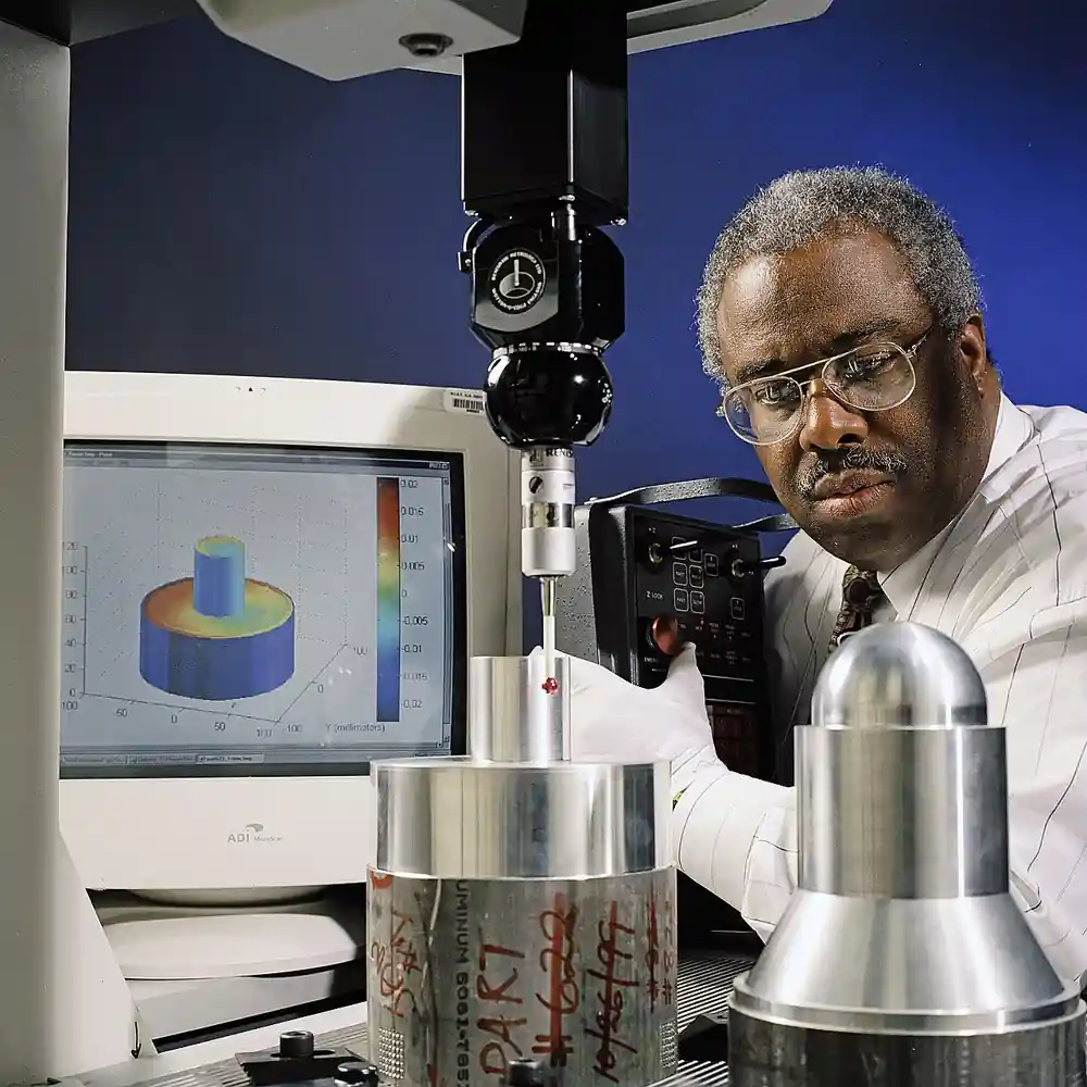
A gantry coordinate measuring machine is a Cartesian measuring instrument in which a horizontal beam rides on two upright columns that travel along rails fixed to the floor or to a massive granite base, with the spindle carriage moving along the beam to reach any point in a large measuring volume. The architecture exists because moving a two-ton aerospace skin panel or a welding fixture under a bridge type machine is impractical, while moving a comparatively light carriage over a stationary part is not. Volumes start near 2 x 3 x 1.5 m for entry floor-anchored machines and extend past 6 x 12 x 3 m in shipyard and wind turbine scale installations.
Engineers who buy gantry systems work in aerospace structures, automotive body and battery tooling, wind turbine components, marine propulsion, rail car sections, and large molds. The purchase is dominated by four engineering decisions that smaller coordinate measuring machine purchases never face at the same severity: the foundation, because a gantry derives its straightness from rails grouted to a floor that must not move by more than a few tens of micrometers; the thermal strategy, because a 4 m steel or ceramic beam grows about 40 um per deg C, which is catastrophic against a 10 um tolerance; the drive and encoder map, because a 6 m travel exposes scale and straightness errors that a 500 mm bridge travel hides; and the part logistics plan, because loading a gantry with a crane defines the machine hall as much as the machine does.
This page treats the gantry coordinate measuring machine as a capital purchase with a specification trail: how the architecture works, what ISO 10360 verification actually measures on a large machine, which probe systems and drive technologies separate one class of gantry from another, and what a defensible RFQ must state about foundation, temperature, accuracy, and throughput. It is written for the engineer who signs the acceptance test, not for a general audience.
Chapter 1 / 06
What a Gantry CMM Is and What Is Being Decided
The gantry architecture places the guide rails of the longest axis on or in the floor, so the range of that axis is limited only by the length of rail a customer is willing to pour concrete for. The moving crossbeam spans the two rails on upright columns; the carriage rides the beam for the second horizontal axis; and the spindle moves vertically for the third. Some designs add a horizontal ram extension for the fourth axis to reach around deep structures. This contrasts with the bridge CMM, whose entire bridge rolls on a table or on side ledges and whose practical ceiling sits near 1.5 m spans and 3 to 4 m lengths, and with the articulated arm CMM, a portable 6 or 7 axis device whose single point probing covers large components at lower accuracy. The gantry is the machine class between bridge machines and laser trackers: more accurate than a tracker on tight toleranced point clusters, more volume than any bridge.
What is being decided in a gantry purchase is therefore not mainly the machine; it is the measurement infrastructure. The buyer commits to a foundation block, commonly 0.5 to 1.5 m of reinforced concrete isolated from the shop slab, on which the rails are grouted and leveled. The buyer commits to a thermal envelope, because the machine class performs to catalog only inside a temperature window that vendors state as 18 to 22 deg C with limits on gradients, typically 0.5 to 1.0 deg C per meter and per hour. The buyer commits to part handling, because a machine that measures a wing rib is fed by crane or by heavy transport, and the loading path must clear the rails. And the buyer commits to the software and datum strategy that make results traceable, because on parts this large the alignment datum choice changes measured geometry by more than the machine error.
Inside dimensional metrology the gantry sits at the top of the contact measuring hierarchy for large components. Its native probing is a touch trigger probe or a scanning probe mounted in the spindle; many installations add an indexable head so one setup reaches multiple part faces. Noncontact extensions exist: machine mounted industrial camera systems and laser line scanners cover freeform sheet metal at the cost of a looser uncertainty statement. What the class retains from smaller machines is the Cartesian meter traceability chain: glass or magnetic scales on each axis, compensation maps for straightness, squareness, and yaw measured at commissioning, and a probe calibration routine that ties stylus tip geometry to the spindle datum. The best installations publish a measurement uncertainty budget per feature type, not a single machine number.
The decision context also includes what the gantry replaces. Large parts otherwise go to a laser tracker, which measures at 15 to 60 um over meters with careful setup and operator skill, or to fixed gauge fixtures, which are fast but frozen to one part number. A gantry capital purchase is justified when the part mix changes faster than fixtures can be built, when tolerance stacks demand volumetric accuracy that a tracker only achieves with effort, or when scanning thousands of points per surface per shift is routine. Conversely, when parts exceed about 20 m or ship between sites, the tracker or a portable arm remains the tool; no one gantrifies a ship hull. Small precision parts stay below the argument entirely, where an optical comparator or a shop microscope settles dimensions faster than any full machine.
A final framing observation: gantry machines are bought by risk, not by catalog page. Two vendors may quote identical 3.5 x 6 x 2 m volumes with similar stated accuracy, and the machine that passes its ISO 10360 acceptance on the customer floor, on the customer parts, at the customer temperature, is the one whose compensation strategy and service organization were engineered for that floor. The chapters that follow are organized around the numbers that separate those two quotations: volumetric length measuring error, probe qualification behavior, thermal compensation, rail straightness, and the acceptance protocol written into the contract.
Chapter 2 / 06
How the Machine Achieves and Holds Accuracy
Accuracy in a gantry begins with geometry that no software can repair. Each axis rides on precision guide ways; in premium machines these are granite beams or lapped steel rails carried on granite or polymer concrete piers, and straightness over 6 m is held to a few micrometers. The machine measures axis displacement with linear encoders, glass scale or magnetic, whose resolution runs 0.01 to 1 um depending on class. Every geometric deviation that remains after manufacturing, including pitch, yaw, roll of each axis, straightness in two planes per axis, and squareness between axes, is mapped at the factory and again at installation, then compensated in the controller. The residual after compensation is what the ISO 10360 verification measures, and it is the only number a buyer should accept as the machine accuracy.
The standard framework is ISO 10360, the multi-part standard for acceptance and reverification tests. The parts a gantry buyer cites are part 2 for length measurement error with a touch trigger probe, E0,MPE expressed as a bandwidth such as 2.5 + L/300 um; part 20 or scanning specific parts for scanning error where scanning probes are fitted; and the newer sections covering probing systems and rotary tables where applicable. A typical premium gantry quotes E0 near 2.0 + L/250 um, mid-range machines near 4 to 6 + L/150 um, and economy long-travel machines near 8 to 12 + L/100 um, with L in millimeters. On a 3 m diagonal step gauge measurement those bands translate to about 12, 25, and 40 um respectively, which is exactly the spread between passing and failing an aerospace contour tolerance.
Probing is the second half of the accuracy story. A touch trigger probe registers a point when the stylus deflects enough to break a mechanical or electrical contact, with pretravel that is repeatable to a fraction of a micrometer after qualification; a scanning probe maintains controlled contact and streams hundreds to thousands of points per second, enabling form evaluation that trigger probing cannot support. Both must be qualified on a calibrated reference sphere before use, and stylus changes restart qualification. On a gantry the probe head is usually motorized and indexable, so the effective stylus reach and orientation error budget varies by head position; a competent acceptance test exercises the head positions actually used in production programs, not only A0 B0.
Thermal behavior dominates long-term accuracy. A steel beam of 3.5 m grows about 41 um per deg C; aluminum grows about 79 um per deg C over the same span; a granite base moves far less. Machines manage this by material choice, ceramic or granite beams on premium platforms, by staging scales and structure symmetrically so growth is common mode, and by active compensation using temperature sensors on the structure mapped into the scale readings during each move. The buyer verifies thermal behavior by reading the machine's own error during a slow temperature drift: a well compensated machine holds its step gauge reading to a few micrometers across a 1 deg C swing, and an uncompensated machine walks tens of micrometers. NIST technical notes on coordinate measuring machine performance describe the test patterns and uncertainty treatment behind such checks, and the references listed at the end of this page carry the method.
Dynamic effects set throughput limits and appear in the verification as scanning and scanning probing errors. Accelerating a 400 kg carriage along a 6 m beam excites structure vibration that the controller must settle before a probe point is valid; vendors publish maximum probing rates and accelerations, and scanning quality is specified at stated speeds, not maximum speed. A practical acceptance practice includes a scanning run on a calibrated sphere at production speed, comparing the quoted scanning probe error against the measured radius spread. Where the gantry carries a laser scanner or camera head, the same logic applies: verify on a known artifact at working standoff and speed, because a sensor that meets specification at 10 mm per second and fails at 80 is a scheduling problem disguised as a metrology problem.
Finally, part and fixture elasticity interact with machine accuracy in ways the catalog cannot state. A thin aerospace skin clamped to a cart sags between supports; the gantry measures that sag faithfully and reports out of tolerance geometry that the airframe will not see once fastened. The metrology engineer owns the support scheme, the datum simulation, and the gravity compensation logic, usually decided jointly with the design authority before the machine order is placed, because the fixture cart design is part of the machine contract in most gantry installations.
Chapter 3 / 06
Types, Construction, and Duty Boundaries
Gantry machines divide by where the rails live and how the beam is supported. The classic floor rail gantry anchors both rails in the foundation, giving unlimited length and open access for cranes; the machine can straddle a fixed part or even a pit. The single column "moving bridge" economy pattern scales the architecture down to 1.5 x 2.5 x 1.6 m class volumes for mold and foundry work. Premium versions place the rails on a granite or polymer concrete base for thermal stability at moderate volumes, trading the unlimited length of floor rails for better environmental resilience. A fourth family adds a fourth horizontal axis ram for reaching deep pockets in spar and fixture work, with ram extensions to 1 m or more.
Drive and bearing technology separates price classes more sharply than volume does. Rack and pinion drives with linear guide rollers carry the largest beams at moderate cost and achieve positioning good enough after compensation for most airframe tolerances; linear motors drive premium machines with smoother motion and better scanning dynamics at higher cost and tighter air gap tolerances; ball screws appear on smaller single column machines. Air bearings, used on some premium platforms, average guide errors and are exceptionally clean but demand stable floor air; recirculating roller bearings tolerate shop reality and are the default on industrial gantries. None of these choices is visible on a datasheet front page, and all of them predict the service profile: a rack drive gantry in a fabrication shop is a workhorse that absorbs contamination; a linear motor machine near grinding operations needs enclosure discipline.
Probe and sensor outfits define what the machine can actually measure. The baseline is an indexable touch trigger probe with a stylus set, covering datum establishment, hole positions, and discrete points. Production aerospace and automotive tooling installations add a scanning probe for form and contour, and many add an optical distance sensor or laser line scanner head for sheet metal and castings. Machine vision integrations using an industrial camera head cover fiducial and character verification at coarse tolerances; a dedicated vision measuring machine remains the better tool for sub millimeter electronics. Rotary tables integrate into some gantries for turned large parts, and change racks store heads and stylus clusters so long programs run unattended through head swaps.
Duty boundaries are concrete. A gantry does not replace a tactile bridge machine for tolerances below roughly 10 um on small parts; the fixed structure of a top bridge CMM with E0 near 1 um outclasses it. It does not replace a gauge block stack or a surface plate routine for shop floor checks; those are touched in the machine's calibration, not replaced. It does not replace a surface roughness tester for texture, because the probe and filters differ, nor a laser tracker where the part exceeds the volume or must be measured in place on the aircraft. It complements each: the gantry is the volumetric authority in the building, and the peripheral instruments carry their own domains.
Environmental boundaries decide success as often as machine class. Vibration from presses, cranes, and transport traffic couples into the rails; vendors specify floor vibration limits, and isolators or a separated foundation block are the standard remedies. Air quality matters for air bearings and for laser scanners. Temperature is the master variable: a fabricating hall cycling 8 deg C overnight cannot support catalog accuracy on any gantry, and the honest options are an enclosure around the machine with its own conditioning, part soak scheduling with measured part temperature, or accepting a wider uncertainty statement. Compressing the uncertainty discussion into the purchase contract is what separates a metrology authority from an expensive crane support structure.
The construction map below pairs common large part duties with the gantry configuration that survives them and the configuration that generates rework and argument.
Duty
Suitable configuration
Configuration to avoid
Aerospace skin and spar contours, 10 to 50 um tolerances
Floor rail gantry, scanning probe, thermal compensation, part temperature sensing
Rack drive economy machine without part temperature input
Automotive body and battery fixture certification
4 to 6 m gantry, indexable head, laser scanner plus touch probe, two shift programs
Bridge CMM at volume limit with fixture overhang risk
Wind component hub and blade root inspection
Long floor rail gantry 4 to 10 m class, rugged enclosure, roller bearings
Premium linear motor machine in uncontrolled hall (thermal drift eats accuracy)
Large mold and foundry pattern work
Single column moving bridge 1.5 to 2.5 m class, trigger probe, open shop air filtration
Air bearing machine beside grinding debris without enclosure
Marine and rail section layout
Gantry with extended ram and tracker hybrid setup, coarse tolerance programs
Tight tolerance scanning programs without datum strategy agreed with design
In place aircraft or ship survey beyond hall limits
Laser tracker or portable arm, not a gantry
Any fixed machine asked to travel to the part
Chapter 4 / 06
Key Specification Parameters
The decode table lists the parameters that decide whether a quoted gantry will pass acceptance on the buyer floor and hold its numbers over years. The commentary after the table states what to demand in the quotation for each line.
Attribute
Typical range or options
What it decides
Measuring volume X x Y x Z
2 x 3 x 1.5 m to 6 x 12 x 3 m; ram adds 0.5 to 1.2 m reach
Part envelope, hall footprint, crane clearance, and price class
Length measuring error E0,MPE
2.0 + L/250 um premium to 12 + L/100 um economy
The tolerance families the machine can arbitrate at acceptance
Probing error, trigger
1.5 to 4 um MPE form on sphere
Point repeatability behind position tolerances
Probing error, scanning
2.5 to 8 um at stated speed
Form and contour capability and scan throughput
Drive and bearings
Linear motor, ball screw, rack and pinion; air or roller bearings
Dynamic quality, contamination tolerance, service profile
Thermal compensation range
16 to 26 deg C window typical; sensors on beam and part
Whether catalog accuracy survives the buyer hall
Axis speed and acceleration
20 to 60 m/min beam; 0.3 to 1.0 g class carriage
Cycle time on sparse point programs and long scans
Probe outfit
Indexable trigger head, scanning head, laser line, camera
Feature coverage: datum, form, freeform, fiducial
Foundation requirement
0.5 to 1.5 m isolated slab; rail grout and level tolerance
Civil cost, schedule, and long term straightness retention
Controller and software
Vendor CNC with compensation maps; GD&T evaluation package
Programmability, reporting, and integration with plant quality systems
Volume deserves honest treatment: stated X x Y x Z is the clear measuring envelope with standard stylus, and deep parts may steal Z reach through head extension. Buyers measure their worst part plus fixture height plus probe clearance before comparing volume lines. On price, volume scales the machine roughly linearly in rail length but superlinearly once beam mass forces the next drive class; the honest RFQ states the true minimum envelope, not a round number inherited from the last machine.
The accuracy lines are contract lines. E0,MPE and probing error MPE must be quoted with the standard part and test per ISO 10360, and the acceptance protocol in the contract should repeat the same test on the customer floor after installation, on customer artifacts where possible. Quotations that quote only "volumetric accuracy" without the standard reference, or that quote accuracy at 20.0 deg C dead steady with no compensation statement, are not comparable to those that quote the ISO bandwidth. A step gauge or ball bar based reverification schedule, annually or after any collision or relocation, belongs in the same contract.
Throughput parameters interact with the program mix. A gantry certifyng 200 datum points per fixture lives on indexable head speed and approach strategy; a contour scanning program lives on scanning speed at stated error, which vendors list separately from maximum traverse; a laser scanner program lives on line rate and standoff window. The RFQ should include a representative part program or two and ask for a cycle time quote, because the datasheet axes do not predict duty cycle on real geometry, and idle head changes can dominate a shift.
The foundation and environment lines convert site risk into contract language. The quotation should include the vendor's foundation drawing with slab thickness, reinforcement, isolation joint, and rail level tolerance, plus the temperature, gradient, and vibration envelope within which the accuracy statement is valid. Where the hall cannot meet the envelope, the same vendor package should price the enclosure and conditioning option. Leaving these as site responsibilities is how gantry acceptance tests fail at the last moment with no party accountable.
A cost planning table for the main machine classes follows; figures are budget planning ranges in USD for the machine and standard probing only, excluding foundation, enclosure, and installation, and they move materially with options and volume.
Class
Volume example
Machine budget range USD
Economy floor rail, rack drive, trigger probing
2.5 x 4 x 1.8 m
350,000 to 600,000
Mid range gantry, roller bearings, scanning probe
3.5 x 6 x 2.0 m
700,000 to 1,200,000
Premium linear motor, thermal compensation suite
4 x 8 x 2.5 m
1,500,000 to 2,800,000
Largest shipyard and wind class installations
5 x 12 x 3 m
3,000,000 to 6,000,000
Site works: foundation, enclosure, conditioning, crane
per project
150,000 to 800,000
Service contract, verification, map refresh
annual
20,000 to 60,000
Chapter 5 / 06
Selection Decision Factors and RFQ Language
The selection sequence below compresses the chapters above into an ordered decision list a team can walk in one meeting and turn directly into RFQ text.
Fix the part envelope: largest part, fixture height, probe and head clearance, and growth margin for the next part generation; state X, Y, Z from measured parts, not from folklore.
Fix the tolerance families to be arbitrated: tightest contour, position, and form tolerances with their datums; choose the machine class whose E0 and probing MPE sit at or below one third of the tightest tolerance.
Audit the site before shortlisting: hall temperature swing and gradients, vibration sources, floor capacity, crane coverage, and air quality; price enclosure and foundation remedies now, not after award.
Choose probing by feature mix: datum and hole work on trigger probing; contour and form demand scanning; sheet metal and castings justify laser line or camera extensions with their own verification artifacts.
Demand ISO 10360 lines quoted with conditions, and write the acceptance test into the contract: on site, on standard artifacts, at production temperature, with customer program cycle times.
Plan the fixture and datum strategy with design engineering before order: cart structures, support schemes for compliant parts, datum simulation, and gravity compensation rules.
Compare service reality: map refresh interval, collision policy, spare lead times, remote diagnostics, and training; a gantry is a decade plus commitment and the vendor's metrology bench matters as much as the machine.
Write the RFQ with volumes, tolerances, site envelope, probing, acceptance protocol, reporting and integration requirements, and a two program cycle time exercise.
Side by side, the two quotations that survive most shortlists differ in exactly the ways this page has emphasized, and the table below shows how the same nominal volume reads across classes.
Attribute
Economy floor rail
Mid range gantry
Premium linear motor
E0,MPE, 3 m diagonal example
about 40 um
about 25 um
about 12 um
Scanning probe error on sphere
not fitted typically
4 to 8 um
2.5 to 4 um
Thermal compensation
scale sensors basic
beam and scale sensors
beam, scale, and part sensors with drift model
Contamination tolerance
high, roller bearings
high
moderate, air gap and optics discipline
Unattended shift capability
limited, manual head
change rack option
change rack and auto calibration standard
Typical duty found
foundry, layout, weldments
tooling, molds, wind
aerospace structures, battery tooling
The RFQ block itself should carry: machine class and volume; tolerance families with datums and part families; probing and sensor list with verification artifacts; ISO 10360 acceptance lines with on site retest; site envelope statement or remediation quote; foundation drawing and rail level tolerance; cycle time exercise on two supplied programs; reporting formats and integration with the plant quality system; training days; service response and map refresh terms; and the long term verification schedule using step gauge or laser interferometer per vendor method. A quotation returned without the acceptance protocol accepted in writing is incomplete; every professional vendor in this class expects exactly these questions, and the ones that bristle at them are answering the selection question for the buyer.
Chapter 6 / 06
Installation, Standards, Failure Modes, and Maintenance
Installation sequencing is a project in itself. The foundation is poured, cured for the specified period, commonly weeks, and the rail bases are grouted and leveled to the vendor tolerance, which on long machines is expressed per meter and cumulatively. The gantry is erected, geometry mapped, and compensation loaded; then the machine soaks thermally with the hall held in envelope before acceptance runs. Part carts and fixtures arrive next, and the first production programs are proved out with the quality team. Experienced buyers hold retention against the acceptance protocol, because the moment of truth is the ISO 10360 run on the customer floor, not the factory report.
The standards stack for this class is compact and worth citing verbatim in contracts. ISO 10360 governs acceptance and reverification, with part 2 the default citation for length measurement error and the scanning and probing parts for sensor equipped machines. ISO 14253 governs decision rules for proving conformance with measurement uncertainty, the document that settles whether a measured 0.11 on a 0.10 tolerance is a reject. ISO/TS 15530 covers uncertainty evaluation for coordinate measurements on real parts, the method behind honest feature specific budgets. Vendor internal standards cover rail grout, air quality for air bearings, and map refresh. Where a national metrology institute such as NIST has published technique notes on machine performance assessment, they serve as method references for witness tests, and two such references are listed among the sources.
Failure modes in gantry service cluster into five families. Collision damage leads the list: a program error driving the stylus into a fixture cart bends shafts and loads the head; mitigation is simulation before first run, reduced speed first articles, and a collision policy in the service contract that includes remapping after any significant strike. Thermal drift, covered in chapter 2, appears as morning to afternoon bias; mitigation is part soak scheduling, part temperature sensing, and periodic step gauge checks logged as a control chart. Rail contamination and bearing wear appear as noise and flat spots in straightness; mitigation is air filtration discipline and scheduled guide cleaning. Encoder and cable faults appear as lost position alarms and are resolved by service; spare encoders for long travel axes justify their shelf space. Software datum errors, the largest source of wrong results in practice, are mitigated by locked program revisions, datum simulation reviewed with design, and periodic measurement of a reference artifact as a program sanity gate.
Maintenance follows the machine class. Daily: probe qualification at shift start, stylus condition check, and reference sphere clean. Weekly: guide way cleaning and air filter differential check where fitted. Monthly: verification run on a step gauge or ball bar with results charted; the chart is the machine's health record and the arbiter in any accuracy dispute. Annually: full ISO 10360 reverification by the vendor or an accredited laboratory, map refresh if drift exceeded thresholds, and calibration of the part temperature sensors. Across a decade, budget items include probe head rebuild, stylus replacement after wear or collisions, controller battery and UPS replacement, and one mid life laser or camera sensor recalibration at the manufacturer.
The operational habits that protect the investment are organizational rather than mechanical: one accountable metrology engineer; a written part program change control; training records for every operator; the control chart discipline on verification artifacts; and a standing relationship with the vendor's applications bench for new part families. A gantry that is managed this way holds its acceptance numbers for a decade and outlives two generations of the parts it was bought to measure, which is the actual standard of success for capital dimensional metrology.
FAQ
What accuracy can I realistically expect from a gantry CMM?
Expect a length measuring error bandwidth of about 2.5 + L/250 um on premium machines and about 4 to 12 + L/100 to L/150 um on mid range and economy classes. On a 3 m measurement that means roughly 12 um on premium machines and 25 to 40 um on standard industrial classes, verified to ISO 10360 on your floor. Tighter claims should be read with their thermal and installation conditions attached.
Do I need a special foundation for a floor rail gantry?
Yes. Vendors specify an isolated reinforced slab, commonly 0.5 to 1.5 m thick, separated from the general shop floor, with rails grouted and leveled to a per meter straightness tolerance. The foundation protects rail geometry from truck and crane traffic and from slab curl. Budget it as a separate line; site works of 150,000 to 800,000 USD are typical depending on hall condition.
How much does temperature really matter on a large gantry?
It is the dominant error source. A 3.5 m steel beam grows about 41 um per deg C, and a hall cycling several degrees can move results by more than the machine error band. Machines compensate with beam, scale, and part temperature sensors, but the accuracy statement still assumes an envelope such as 18 to 22 deg C with gradients under 0.5 to 1.0 deg C per meter. Outside that envelope, widen your uncertainty statement.
Should I buy trigger probing, scanning, or a laser scanner on the gantry?
Match sensors to features. Trigger probing covers datums, holes, and sparse points; scanning adds form and contour capability with probing errors of roughly 2.5 to 8 um; laser line scanners cover freeform sheet metal quickly at looser uncertainty, typically tens of micrometers with artifact verification. Most aerospace and tooling installations combine an indexable trigger or scanning head with one scanning sensor and verify each on calibrated artifacts at production speed.
When is a laser tracker the better choice than a gantry?
Choose the tracker when parts exceed the largest practical gantry volume, must be measured in place on the aircraft or structure, or arrive too rarely to justify a fixed machine. Tracker accuracy of about 15 to 60 um over meters suits fixture build and large assembly verification. The gantry wins on dense point and scanning programs, tighter volumetric tolerances, and unattended repeated measurement of a stable part mix.
What should the acceptance test include before I sign?
An on site ISO 10360 run: length measuring error on a step gauge or ball bar along several diagonals, probing error on a calibrated sphere in the head positions you use, and a scanning test at production speed if scanning is fitted. Add a cycle time run on two of your real programs and a thermal drift check across a hall temperature swing. Hold retention against this protocol; the factory report alone does not establish floor performance.
What does annual maintenance and reverification cost?
Plan on an annual service and verification budget of roughly 20,000 to 60,000 USD including vendor ISO 10360 reverification, map refresh when drift thresholds trip, and probe service. Keep a control chart from monthly step gauge or ball bar checks between visits; it catches drift early and provides the evidence base for any accuracy dispute over the machine's life.