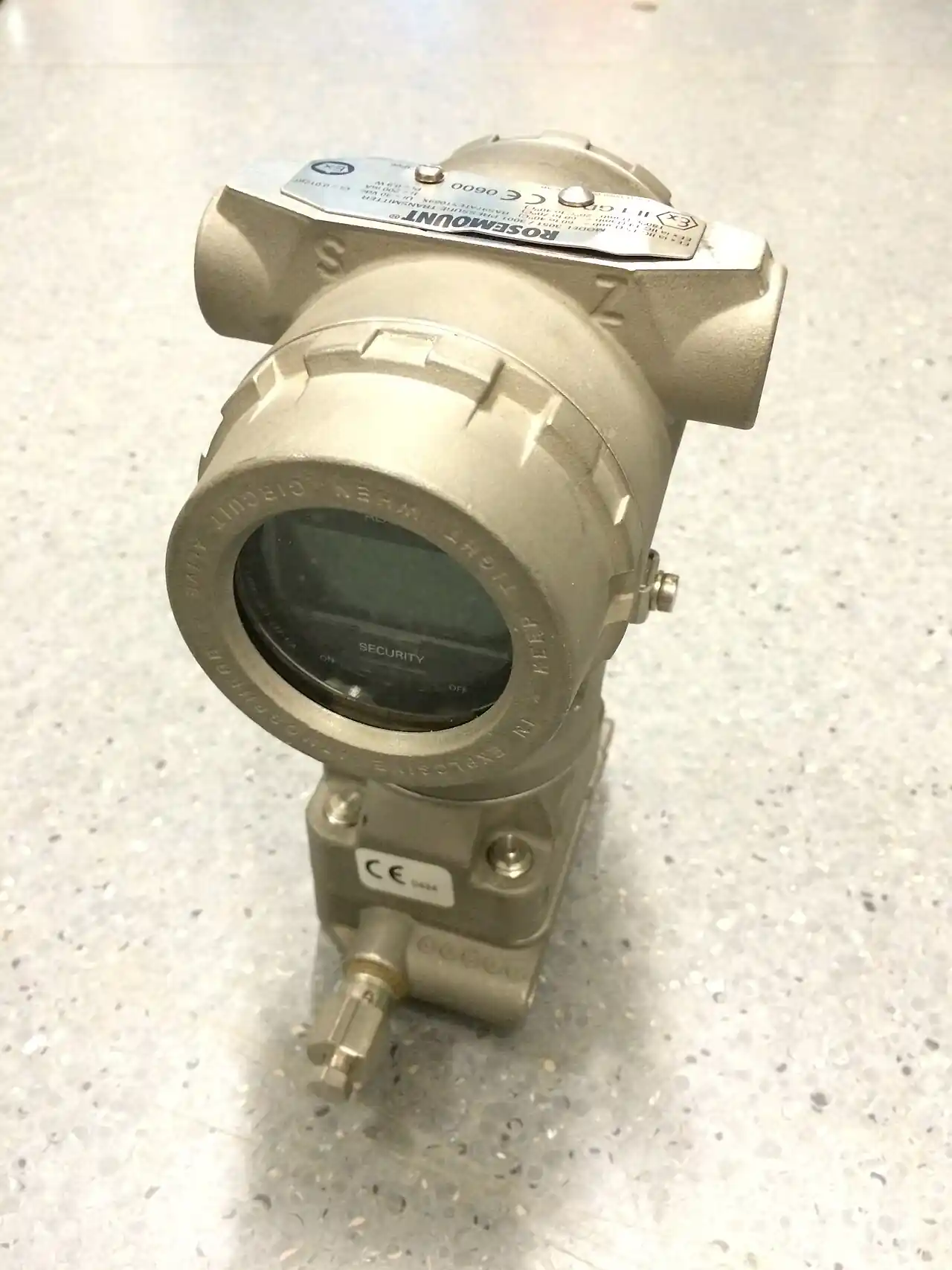
An instrument manifold is the compact block of small valves that stands between the process impulse lines and a pressure or differential pressure transmitter, giving the instrument its three working verbs: isolate, so the transmitter can be removed or serviced with the line live; equalize, so both sides of a differential pressure cell can be joined at the same pressure and the loop zero checked in place; and vent or drain, so trapped pressure is released safely and impulse legs are blown down to atmosphere or a collection pot. It is the component that turns a pressure transmitter from a welded-in sacrifice into a maintainable instrument: the two, three, or five valve block, direct-mounted on the transmitter's flange or piped beside it, is where every calibration, every zero check, and every transmitter change in the plant's life is actually performed, and its leak-tightness is the wall between the process and the instrument technician.
Specifying one is four linked decisions: the valve count that matches the measurement, two valves for gauge pressure duty, three for the classical differential pressure transmitter with remote venting, five for full in-place vent and drain; the interface, direct-mount flange dimensions to IEC 61518 or threaded connections with the plumbing that implies; the pressure, temperature, and materials envelope against the process, stainless steel the default, 6,000 psi class ratings the norm; and the valve style and seal chemistry inside, needle or ball pattern, soft seats for bubble-tight shutoff against the thousands of cycles a decade demands. This page works each decision with catalog numbers and closes with the RFQ lines that make manifold quotes comparable at engineering level.
This page treats the instrument manifold as the maintenance interface of pressure measurement: two, three, and five valve arithmetic, isolate-equalize-vent routines, direct mount interfaces to IEC 61518, seat and seal chemistry against cycle life, and the RFQ lines that carry the specification.
Chapter 1 / 06
What an Instrument Manifold Is and What Is Being Decided
The hardware is a drilled stainless block with a handful of small valves. Each valve is a needle, a finely threaded stem with a tapered or ball tip seating into a port, or a quarter-turn ball; the block's drillings route process pressure from the impulse connections to the transmitter ports and provide the cross-connections and vents the configuration needs. A two-valve manifold carries one isolate and one vent for a gauge pressure transmitter. A three-valve manifold carries two block valves, high and low, and one equalizer between them, the classical companion of the differential pressure transmitter. A five-valve manifold adds two vents or drains to the three-valve pattern, so the technician can bleed each side independently without opening the transmitter's drain plugs. Behind the valve count, every manifold is the same promise: the process stays in the block while the instrument comes out.
What is being decided at purchase is the maintenance geometry of the measurement point. First, the valve count from the measurement's physics: gauge pressure wants two valves; differential pressure, across an orifice plate flowmeter primary or a filter or a pump, wants three at minimum and five where in-place venting is worth its price. Second, the interface: direct-mount manifolds bolt straight onto the transmitter's process flange, with the mating dimensions standardized in IEC 61518, eliminating tubing, fittings, and their leak paths; remote-mount manifolds thread onto impulse tubing where the transmitter stands away from the tap, and buy vibration and temperature distance at the price of plumbing. Third, the envelope: process pressure and temperature against the manifold's rating, commonly 6,000 psi class for standard blocks, with the body, stem, and seat materials chosen for the chemistry. Fourth, the valve style and seal: needle valves for metered, gentle operation, ball valves for quick quarter-turn action, and the seat chemistry, PCTFE and PEEK families, that holds bubble-tight through the decade's cycles.
The competitive frame is mostly internal to the installation. Against no manifold, a transmitter threaded or flanged naked to the process, the manifold wins the first time the instrument needs service: the naked installation must be isolated by a separate pipe valve and vented by cracking a fitting, and on a differential measurement the naked installation has no honest zero at all. Against discrete needle valve assemblies plumbed from parts, the manifold wins on leak paths, every tubing joint eliminated is a joint that cannot weep, on envelope compactness, and on the standardized routines the technicians can be trained on once. Against the transmitter's own integral vents, where a maker offers them, the five-valve manifold keeps the routine outside the instrument housing and universal across fleets. And against the valve families of the process world, the ball valve and needle valve pages, there is no contest of duty: the manifold is an instrument-grade component, small orifices and fine threads, and never a substitute for process isolation; the lock-out that protects the technician opening the manifold for transmitter removal is a process valve, and the manifold is the second wall, not the only one.
One positioning note: this page is the single-product page for the valve block itself. The pressure transmitter, the differential pressure transmitter, and the gauge and absolute pressure transmitter families it serves each have their own pages, as does the orifice plate flowmeter primary whose impulse lines it drains; here the assumption is the maintenance interface of a pressure-class measurement, and every number that follows is chosen for that world.
Chapter 2 / 06
How the Valves Isolate, Equalize, and Vent
The verbs are three, and each is a valve-opening sequence a technician performs from muscle memory. Isolate: the block valves close, the process pressure stops at the manifold's seats, and the transmitter side becomes a closed volume that can be vented and opened. Equalize: on a three or five valve block, opening the equalizer with both blocks closed joins the high and low sides at one pressure, and the differential pressure transmitter should read zero: this is the in-place zero check, the routine that catches span drift, sensor damage, and loop errors without removing anything, and the reason the three-valve pattern is welded into the industry's habits. Vent: the vent or drain valves release the trapped transmitter-side pressure to atmosphere or a pot, making the instrument safe to remove, and in blowdown duty, with the process side valved and the vent opened to flow, they clear impulse legs of condensate and deposits back toward the process tap.
The sequences have a discipline that safety writes. The zero check on a three-valve manifold: close the high block, close the low block, open the equalizer, read the transmitter's zero against the reference, close the equalizer, then open the low block and the high block in that order, the order matters because opening high last presses any trapped equalizer volume back into the low side symmetrically rather than stepping the cell. Transmitter removal: close both blocks, open the vents to release trapped pressure, verify the gauge if one is fitted, then unbolt. Return to service: vents closed, blocks opened, low first, and the loop checked against the process. Every plant prints these on the loop folder; every manifold that fights them, unlabeled handwheels, reversed stems, vents plumbed to nowhere, is a training accident scheduled. The labeling line belongs in the RFQ: block, equalize, and vent marked on the block, or better, on tags the technician reads in the dark.
The valves themselves are small machines with catalog honesty. The needle pattern: a hardened stem with a tapered tip, or a rotating ball tip on gentler designs, driving onto a seat; the thread pitch and handle size set the closing feel and the metering character when cracked open for blowdown; the stem seal, packing or welded metal bellows on emission-grade designs, holds the process at the stem. The ball pattern: a quarter-turn ball with a bore, fast and unambiguous, favored on vent duty and on offshore practice. The seats: PCTFE and PEEK families hold bubble-tight across thousands of cycles and the chemical window, graphite and metal seats carry the temperature extremes at some seat class cost. Cycle life is a datasheet number worth demanding, quality blocks quote thousands of cycles at rated pressure with no seat degradation, and the rebuild kit, stems, seats, packing, prices the manifold's second decade.
The block's pressure arithmetic closes the chapter. The manifold sees full process pressure on the process side and near-atmosphere on the vent side, so its rating is a static envelope, commonly 6,000 psi class at ambient derating with temperature to 120 deg C standard and higher by design, and its test evidence, hydrostatic shell and seat tests, is the maker's certificate. The bores are small, a few millimeters, so the trapped volumes between manifold and transmitter cell are tiny, which is exactly what the zero routine wants, a tablespoon of fluid whose compression and thermal expansion are negligible against the cell's range. The small bores also mean the manifold is not a flow component: it meters vent flow through a needle as a safety virtue, and it must never be specified as if it were a bypass or a needle valve in the process line, a duty its orifices and seats were never asked to carry.
Chapter 3 / 06
Types, Construction, and Duty Boundaries
Construction divides by interface and by severity. The direct-mount manifolds bolt to the transmitter: traditional in-line flanged patterns that mate to the transmitter's process flange with the impulse connections threaded into the manifold's face, and the coplanar patterns that sandwich flat against the coplanar transmitter face for the lowest installed volume; both follow the IEC 61518 mating dimensions, so manifolds and transmitters from conforming makers assemble without adapters. Remote or pipe-to-pipe manifolds thread into impulse tubing on a bracket beside the transmitter, serving the hot, vibrating, or access-constrained installations where the instrument stands back from the tap. Bodies are stainless steel, 316 and 316L the default, with higher alloys for sour and chloride service by certificate; bonnets and handles are stainless or coated steel; the test plugs and drain ports take the plant's fitting standard. Severity options ladder up: bonnet extensions for hot lines, sealed stem designs for emission duty, steam-rated blocks for saturated service, and the exotic-alloy executions the chemistry demands.
Configurational types are the two, three, and five valve patterns of Chapter 2, plus their relatives: the single-valve blocks for static gauges, the manifold-plus-blind-flange kits that blank one side of a differential cell serving single-sided duty, the combined manifold-with-valve-isolation trains that put a root valve at the tap and the manifold at the transmitter, and the gauge manifolds that serve a pressure gauge with block and vent and often a siphon behind them. The root valve deserves its sentence: the first valve at the process tap, the process-isolation valve proper, is part of the installation even though it is not the manifold, and the manifold's block valves are the second wall; specifying one and depending on two is the discipline, and the loop drawing should show both.
Build
Typical envelope
Duty where it wins
Hard boundary
Direct-mount in-line flanged
IEC 61518 mating, 6,000 psi class
The volume DP installation
Transmitter face must conform
Coplanar sandwich
flat face, minimal volume
Coplanar transmitter fleets
Face pattern lock-in
Remote pipe-to-pipe
threaded 1/2 or 1/4 NPT
Hot, vibrating, set-back installs
Tubing leak paths return
Two-valve gauge pattern
block and vent
Gauge pressure transmitter duty
No equalize verb exists
Five-valve full pattern
2 block, 1 eq, 2 vent
DP duty wanting in-place vent
Price and handle count
Emission-grade stem designs
packed or bellows, certified
Fugitive-emission service
Certificate and cost
Duty boundaries, sentence by sentence. Differential pressure on orifice primaries, filter and pump differentials, level by hydrostatic head: the three or five valve direct-mount pattern owns the duty, and the five-valve earns its price wherever blowdown of impulse legs is routine, dirty fluids, wet gas, seasonal condensate. Gauge pressure transmitters: the two-valve pattern, with the vent doubling as the zero-at-atmosphere check. Static pressure gauges: the single-valve block and gauge manifold families. Steam and hot lines: siphons and cooling legs before the manifold, and the temperature rating honestly read at the operating line, the manifold is not the component that tames heat, the impulse leg is. Severe vibration: remote mounting with the manifold on a bracket and a compliant tubing run, because a direct-mounted block transmits every pipe tremor into the transmitter flange. Emission-controlled and lethal service: the sealed-stem designs with their certificates, and the vent routed to a closed pot or flare path, never to atmosphere, a line the process safety review writes. Cryogenic and high-alloy chemistry: the corresponding executions by certificate. Every boundary is a maintenance-and-safety statement, and Chapter 5 turns each into an RFQ line.
Chapter 4 / 06
Key Specification Parameters
The decode table is the datasheet skeleton. Every row is an RFQ line, and the two right columns are what each row decides and what it costs to leave blank.
Parameter
Typical catalog spread
What it decides
Configuration
1, 2, 3, or 5 valve patterns
The maintenance verbs available
Interface
direct flanged, coplanar, remote threaded
Installed volume and leak-path count
Mating dimensions
IEC 61518 conformity
Transmitter interchangeability
Pressure rating
6,000 psi class typical, derated with temperature
Envelope against the line's maximum
Temperature window
minus 20 to plus 120 deg C standard, higher by design
Seat and seal survival
Body material
316 and 316L, alloys by certificate
Chemistry and sour service legality
Valve style
needle, ball, or mixed
Feel, speed, metering on blowdown
Seat and seal chemistry
PCTFE, PEEK, graphite, metal
Bubble-tight life across the cycles
Connections
1/2 and 1/4 NPT, flanged faces, test plugs
Impulse and vent plumbing scope
Cycle life and rebuild
thousands of cycles, kit priced
Second-decade economics
Certificates
hydro test, material 3.1, emission, Ex where fitted
Acceptance by audit and area rules
The configuration row is the one that decides what the technician can do for the next twenty years. Two valves serve gauge pressure honestly; three give the differential cell its in-place zero; five add the vent-and-drain routine that dirty impulse lines demand, and the price step between three and five is a fraction of one avoided transmitter removal. The configuration is chosen from the measurement's physics and the impulse lines' behavior, wet or dry, clean or scaling, and the loop drawing should show the chosen pattern's handwheels with labels, because the RFQ line and the training page are the same document.
The interface and mating rows decide the fleet's interchangeability. A direct-mount manifold conforming to IEC 61518 bolts to any conforming transmitter face, which is the standardization that lets plants buy manifolds and transmitters from different makers and stock one rebuild kit fleet-wide; the coplanar patterns lock to the coplanar face standard, and the remote patterns trade the standardization for installation freedom. The connections row prices the plumbing scope: thread sizes for the impulse and vent lines, the test plugs where the calibration tap is wanted, and the drain routing, to atmosphere or to a closed pot, which the process safety review has already written. The certificate row closes the delivery ticket: shell and seat test evidence, material certificates to EN 10204 3.1 by project class, the fugitive-emission certificate where the service invokes it, and the Ex marking where any fitted accessory carries one. A quote missing the stack is not cheaper, it is later.
The seat-and-cycle rows are the ones that decide the quiet decade. A manifold's failure is a weeping seat or a packed stem, and both are consumables the rebuild kit answers; the datasheet's cycle-life statement at rated pressure, and the kit's price and availability, are the second-decade economics, and demanding them at purchase costs nothing. The stem seal chemistry and the emission-grade designs answer the fugitive rules where the service is covered by them, and the vent routing, closed pot or flare rather than atmosphere, is the line that turns a routine valve opening into a compliant one.
Chapter 5 / 06
Selection Decision Factors and RFQ Language
The decision sequence runs from the measurement point outward, because every later step prices the earlier one.
Fix the measurement architecture first: gauge or differential, the transmitter's face pattern, direct or remote mounting, and the root valve at the tap as a separate, always-present line.
Choose the valve count from the routines the point needs: two for gauge duty, three for the differential zero check, five where in-place vent and blowdown of the legs is part of the maintenance reality.
Match the envelope: maximum process pressure and temperature against the block's rating curve, the chemistry against body and seat materials, and the impulse medium's behavior, wet gas, condensate, scaling, against the vent and drain provisions.
Fix the interface and connections: IEC 61518 conformity for the direct mount, thread sizes for remote plumbing, test plug provision where calibration taps are the plant habit, vent routing per the safety review.
Choose the valve styles and seals: needle for metered blowdown and gentle service, ball for speed, the seat chemistry for the cycle count and temperature, emission-grade stems where the rules read them.
Plan the human interface: labeled handwheels, handle orientation away from hot lines, access for the tech's hands and torque, and the loop folder carrying the opening sequences.
Close with the commercial lines: test evidence and certificates, cycle-life statement, the rebuild kit part number and price, delivery fitted with the transmitter or separately, and fleet-standardization terms that keep one kit for the fleet.
The cost comparison is leak-path arithmetic wearing a price tag. A direct-mounted manifold eliminates every fitting between process flange and transmitter cell, and every eliminated fitting is a joint that cannot weep, a calibration that cannot drift through a trap, and an hour of maintenance that becomes a minute; the manifold prices against the tubing and fittings it replaces and pays at the first outage. The five-valve step over three prices at a fraction of one avoided transmitter removal on a dirty service. The rebuild kit prices the second decade at a fraction of the block. Against the naked transmitter, the comparison is not economic but moral: the naked installation has no honest zero and no safe removal, and its first service call costs more than the manifold it never had. Table the decision on cost per maintenance action over the decade, and the manifold wins everywhere the instrument is ever touched.
Duty
Configuration to specify
Watch line
Orifice DP flow point
Five-valve direct mount, IEC 61518
blowdown routing, labels
Clean DP, filter or pump
Three-valve direct mount
zero-check sequence training
Gauge pressure transmitter
Two-valve direct mount
vent provision at zero
Hot line, steam-adjacent
Remote mount, siphon ahead
temperature derating curve
Vibrating installation
Remote bracketed block
compliant tubing run
Emission-controlled service
Sealed-stem, certified, closed vent
certificate and routing
The RFQ language that makes quotes comparable, written as the datasheet lines a vendor must answer with numbers: configuration and valve count; interface and IEC 61518 conformity; pressure rating with the temperature derating stated; body, stem, and seat materials named; valve styles per position; connection sizes and test provision; cycle-life statement at rated pressure; certificates, test evidence, material 3.1, emission where invoked; and the rebuild kit part number with price. A quotation answering those lines is a maintenance interface with a guarantee; anything else is a block with handles.
Chapter 6 / 06
Installation, Standards, Failure Modes, and Maintenance
Installation follows the impulse discipline. Mount the block to the transmitter with the correct gaskets or O-rings for the face pattern, torque the flange bolts evenly, and confirm the impulse connections' orientation leaves the vents pointing somewhere safe, a drain funnel, a closed pot, or clear air away from the technician's face. Label the handwheels, block, equalize, vent, at commissioning and keep the labels alive; write the sequences into the loop folder; and orient handles so the routine's order is the ergonomic order. The root valve at the tap closes first and opens last in every sequence, and its handle gets the same labeling care. Heat, vibration, and access get their paragraphs in the loop's installation standard, siphons and set-backs where the manifold would cook, brackets and compliant runs where the line shakes, and platform or ladder access wherever the point is on the maintenance calendar, because a manifold that cannot be reached safely is a transmitter that is never zero-checked. The neighboring instrument disciplines ride the same impulse-and-access culture: the thermowell that carries the point's temperature measurement wants the same reach and the same labeling care, the pressure sensor behind the local gauge shares the tap's discipline, and the flow meter statement of the loop, where one rides the same line, reads the same maintenance calendar.
The standards frame is short and load-bearing. IEC 61518 carries the mating dimensions between differential pressure devices and flanged-on shutoff devices, the standardization that makes transmitter and manifold interchangeable across conforming makers; pressure equipment conformity rides the PED by jurisdiction with the manifold's small volumes usually below the category thresholds but its certificates still demanded by project class; fugitive-emission service invokes the stem-seal certificates where the rules read them; and the material and test evidence answers EN 10204 practice. The loop's functional side, the zero check the manifold enables, belongs to the plant's calibration standard, and the manifold's role in it is exactly one valve sequence long, which is why the training and the labeling are part of the specification rather than decorations.
Failure modes arrive in a predictable order, and each has a specification answer. Seat weep after thousands of cycles shows as a slow zero shift or a process smell at the vent: the answer is the cycle-life statement and the rebuild kit at the scheduled interval, and the seat chemistry honestly chosen at purchase. Stem packing leakage shows as weep at the handwheel on old packed designs: the answer is the seal design's grade for the service and the kit's packing set. Trapped-leg errors, not the manifold's fault but its routine to fix, show as drift on wet legs and seasonal zero shifts: the answer is the blowdown routine actually performed and the five-valve pattern where the legs demand it. Galled stems from cross-threading and overtorque show as handles that spin without seating: the answer is the closing torque discipline, hand-tight plus a firm set, never a wrench, and the training page that says so. Misrouted vents show as oil on the platform or worse: the answer is the routing line in the RFQ and the safety review's signature on the installation drawing. Mislabeling shows as the wrong valve opened at the worst moment: the answer is labels checked at every proof, a minute of commissioning that protects a decade.
Maintenance is a proof and a calendar. Each calibration visit: the zero check through the equalize routine, recorded against the loop's history, and the vents exercised to atmosphere or pot with the process safely blocked. Annually: handwheel action through full travel on every valve, seats observed for weep at working pressure, labels and handle condition confirmed, and the rebuild scheduled when the closing feel or the seat behavior says so rather than when the leak forces it. The rebuild kit, stems, seats, packing, and O-rings, rebuilds the block on the bench in an hour and prices at a fraction of replacement; fleet-standardizing on one maker's patterns collapses the stores list to one kit. Keep the kit count honest: one per critical service and a pool for the fleet is the usual arithmetic.
The commissioning record closes the loop: as-built configuration and interfaces, the sequences printed and posted, the first zero check's values with dates, the vent routing confirmed against the safety review, and the certificates filed against the tag. One page per point, in the loop folder. Plants that keep it zero their cells on schedule; plants that do not discover, at the annual audit, that half their differential measurements have been reading folklore since the last technician who knew the sequence left.
FAQ
Do I need a two, three, or five valve manifold?
Follow the measurement. Gauge pressure transmitter: two valves, block and vent, which also gives the zero-at-atmosphere check. Differential pressure transmitter: three valves minimum, the equalizer enables the in-place zero check. Five valves, adding two vents, wherever the impulse legs need routine blowdown, dirty fluids, wet gas, condensate, and the price step is small against one avoided transmitter removal.
What does the equalize valve actually do?
It joins the high and low sides of the differential pressure cell at one common pressure with both block valves closed, so the transmitter must read zero. That single routine, close blocks, open equalizer, read, close, restore, catches span drift, sensor damage, and loop errors in place without removing anything. It is the reason the three-valve pattern is welded into industry practice.
Can the manifold isolate the process by itself?
It is the second wall, not the only one. The manifold's block valves let you vent and remove the transmitter safely, but the root valve at the process tap is the process isolation proper, and lock-out for intrusive work closes both. Specifying one and depending on two is the discipline, and the loop drawing should show both valves.
Why do makers quote 6,000 psi class?
Because instrument manifolds are small-bore blocks that hold static pressure economically: 6,000 psi class at ambient, derating with temperature, is the industry norm and comfortably above most impulse-line service. The honest reading is the rating curve at your operating temperature, and the test evidence, shell and seat, is the certificate that makes the number real. Never confuse the class with a license to use the manifold as a process valve.
What is IEC 61518 and why does it matter?
It standardizes the mating dimensions between differential pressure devices and flanged-on shutoff devices, the bolt pattern and face geometry where the manifold meets the transmitter. Conformity means manifolds and transmitters from different conforming makers bolt together without adapters, fleets stock one rebuild kit, and interchange survives the next vendor change. It is a one-line RFQ requirement that buys decades of flexibility.
Needle or ball valves inside the manifold?
Needles meter: they open gently, throttle the blowdown stream, and suit the fine control the routines want; they are the default. Balls are fast and unambiguous, quarter-turn, favored on vent duty and offshore habit. Both hold bubble-tight with the right seats, PCTFE and PEEK families, and the choice is feel and speed, not safety class. Mixed patterns, balls as vents behind needles as blocks, are common and sensible.
How often should manifolds be rebuilt?
On evidence, with a calendar as backstop: quality blocks quote thousands of cycles at rated pressure, so the rebuild, stems, seats, packing, typically lands at a midlife service or when the closing feel softens or a seat weeps at proof. Exercise every valve annually, zero-check through the equalize routine each calibration visit, and rebuild on the bench in an hour with the kit. Fleet-standardize on one maker's patterns and the stores holds one kit.