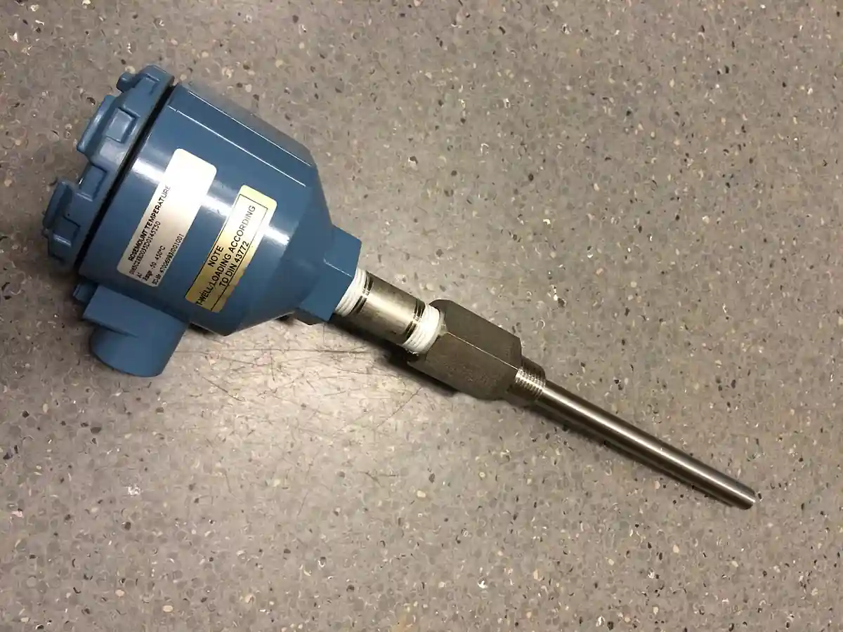
A thermowell is a pressure-tight tube, closed at the process end, that isolates a temperature sensor from the process fluid while placing it in the flow path. The sensor, a thermocouple or an RTD PT100 element, slides into the well bore from outside; the well itself is welded, threaded, flanged, or clamped into the pipe or vessel wall. The well takes the full process pressure, chemistry, and velocity, and the sensor takes none of it, which is why wells exist: sensors can be replaced or calibrated without draining the line, aggressive fluids never touch the sensor sheath, and the assembly holds the pressure boundary when the instrument comes out.
The specification work on a thermowell is mechanical and vibrational rather than electronic. The buyer sizes the well to survive the flow: vortex shedding off the well tip drives it like a tuning fork, and the wake frequency calculation to ASME PTC 19.3 TW decides whether a given stem diameter, immersion length, and material will endure the velocity or fatigue and snap. The buyer matches the material to the chemistry and temperature, chooses the process connection against the pressure class, sets the immersion depth for measurement accuracy, and reconciles the response time penalty the well imposes on the sensor inside it. Those four engineering decisions, plus the sensor interface standard, are this page.
This page treats the thermowell as a pressure and vibration engineered component: how stem and flange constructions divide the family, how wake frequency and stress limits are checked to ASME PTC 19.3 TW, which materials serve which chemistry, how immersion depth trades accuracy against structural margin, and what an RFQ must state so that the well that arrives passes the calculation rather than merely the catalog.
Chapter 1 / 06
What a Thermowell Is and What Is Being Decided
Anatomy first, because the vocabulary carries the specification. The process end of the well, the tip, is closed and machined to a shape: parallel straight stems for general duty, stepped or tapered stems that stiffen the tip region for wake frequency margin, and tapered designs that reduce the shedding force at high velocity. The immersion length, U in the standards, is the length wetted by the process. The lag extension, T, is the un-wetted length that lifts the connection out of hot pipe insulation. The process connection is threaded, welded, flanged, or sanitary clamp. The sensor side terminates in a terminal head, a transmitter head, or a spring loaded sensor holder that presses the sensor tip to the well bore bottom for contact and response.
What is being decided is a chain of four engineering commitments. The first is structural survival: the well must pass the wake frequency and steady stress checks at the worst credible flow condition, or it becomes the component that fatigues at the root thread and writes itself into plant failure statistics; a snapped well vents process fluid at full pressure through the bore it was protecting. The second is measurement honesty: immersion depth sets how far the sensing element sits into the flow, and too shallow an immersion reads the pipe wall instead of the process, an error of degrees that no calibration downstream can remove. The third is compatibility: the well material must outlast the fluid chemistry at temperature, including the crevice at the connection, or the pressure boundary corrodes silently behind insulation. The fourth is response: the well adds thermal mass between process and sensor, and control loops and safety functions that assume a bare sensor speed will oscillate or trip late behind a thick well.
The well sits in the middle of a temperature measurement chain that this site treats in sibling leaves. The thermocouple leaf covers the sensing element, its calibration classes, and the wire systems; the rtd-pt100 leaf covers the resistance element and its accuracy classes; the temperature transmitter leaf covers the signal conversion head that mounts directly on the well. The same instrument suite that buys wells also buys the pressure sensor families, from a gauge pressure transmitter on a header to a differential pressure transmitter across a primary element, and a flow meter whose own installation rules apply; the control side lands in the PLC and SCADA layers where the temperature signal is consumed. This page covers the well: the mechanical component whose failures are pressure and fatigue events, whose cost is set by material and flange class, and whose specification language is dominated by one calculation, ASME PTC 19.3 TW, that every supplier in this market can run and every buyer should demand in writing.
The purchase context differs by industry in ways that change the specification. Steam and power plants run high velocity lines where wake frequency governs everything and flanged, tapered, alloy wells are standard. Oil and gas process lines add hydrocarbon service, sour qualification, and flanged class 600 to 1500 wells with monel or alloy 400 stems in some duties. Food and pharma use sanitary clamp wells with 3-A surfaces and short immersions, often more concerned with cleanability than velocity. HVAC and water service get the commodity threaded stainless wells that the volume market ships by the thousand. The RFQ language below carries the lines that all of these share, and the buyer adds the industry mark relevant to their audit regime.
Finally, the buyer is deciding where the calculation risk sits. Suppliers size wells as a service, and the professional practice is to send the process conditions, fluid, density at operating state, velocity, pressure, temperature, pipe size and schedule, insulation depth, and sensor mass, and receive back the wake frequency ratio, the natural frequency, and the stress margins with the offer. The buyer who buys a catalog well and self-checks the math owns the answer; the buyer who demands the supplier's calculation with assumptions stated shares the engineering, and the paper trail matters exactly once, on the day a well in a high energy line starts to show cracks at the root.
Chapter 2 / 06
Wake Frequency, Stress, and Response Physics
Flow across a cylindrical stem sheds vortices alternately from each side at a frequency given by the Strouhal relationship; for a thermowell the shedding frequency scales with velocity divided by tip diameter. When the shedding frequency approaches the well's natural frequency in bending, the well resonates, and the oscillating stress at the root concentrates at the process connection thread or weld. Fatigue life under resonance collapses from decades to hours. The entire science of thermowell sizing is keeping the shedding frequency safely below the natural frequency, and the industry's agreed method is ASME PTC 19.3 TW, the technical standard that replaced the older Murdock papers with a von Karman vortex based model including the in-line resonance condition.
The standard's outputs are ratios a buyer can read without being a vibration analyst. The wake frequency ratio, shedding frequency divided by natural frequency, must stay below the limit the standard sets with the in-line condition treated; common pass criteria are ratios under 0.4 to 0.5 for the cross-flow condition with the in-line check satisfied, and suppliers quote the number with the pass statement. The steady state stress check confirms the stem survives the drag and lift forces at maximum velocity within the material allowable at temperature. Dynamic stress at the limiting condition is checked for the fatigue margin. When a well fails the check, the remedies are mechanical: increase tip diameter relative to root, use a stepped or tapered profile, shorten immersion, upgrade material strength, or add a support collar in some flanged designs; reducing velocity is a process change and usually not on offer.
Natural frequency scales with the well's geometry in ways the RFQ can use. Frequency rises with tip diameter and falls steeply with immersion length, roughly with length squared; halving a stuck well's immersion more than doubles its margin. This is why high velocity steam lines favor short, stiff, tapered wells, and why the 300 mm immersion that is innocent in water at 1 m per second fails in steam at 40 m per second. The sensor mass inside the bore lowers the natural frequency slightly, which is why the calculation includes the sensor; a heavy thermocouple assembly in a marginal well can flip the verdict, and a change of sensor brand is, in vibration terms, a change of well.
Response time is the second physics the well imposes. A bare sensor responds in seconds; the same sensor in a standard 8 to 10 mm bore well responds in tens of seconds, with time constants commonly 20 to 60 percent slower for the well plus sensor assembly than the bare element, and the exact penalty depends on the annular gap, the contact at the bore bottom, and the fill, air, or solid contact medium. Spring loaded sensors pressed to the bore bottom and reduced bore designs recover part of the speed. Control loops with fast dynamics, compressor anti surge for example, specify response explicitly and design the well for it; most process temperature loops tolerate the standard well without complaint, and the specification exercise is knowing which regime the loop is in.
Conduction error belongs with response because the same geometry causes it. The well stem conducts heat between the process end and the pipe wall, and the sensor reads a mixture of process temperature and wall temperature; the error shrinks with deeper immersion and lower stem conductivity. The classic immersion rules, 10 pipe diameters or insertion to the centerline and beyond by a few diameters, exist to bury this error below the sensor's own accuracy class. Where immersion is limited by wake frequency margins, the buyer is trading conduction error against structural survival, and the honest specification resolves the trade in writing: the accepted measurement uncertainty at the installed immersion, not a silent hope.
Pressure and temperature derate close the physics. The well is a pressure part: its wall holds the full process pressure across the bore, and the allowable span pressure at temperature follows the material's code allowable, with the manufacturer's ratings stated per connection type. Threaded connections seal and hold to their class; welded sockets carry higher pressure; flanged wells follow the flange class, CL150 through CL1500, with the standard's derate at temperature. High pressure gas service adds the catastrophic consequence behind the fatigue check: a snapped well in gas at 100 bar is a jet cutting anything nearby, which is why the wake frequency calculation is not paperwork in that service class.
Chapter 3 / 06
Types, Materials, and Duty Boundaries
Construction types divide along the process connection. Threaded wells, typically 1 inch or 3/4 inch NPT or BSP into a welded boss, are the commodity: economical, replaceable, and rated to their thread class, common in water, air, oil, and general utility service. Welded-in wells, socket welded or seal welded into a weldolet, give the strongest root for vibration duty and high pressure, at the cost of replacement requiring hot work. Flanged wells, typically ASME CL150 through CL1500 raised face, dominate hydrocarbon and steam process duty where removal under isolation matters and the flange rating is part of the line class. Sanitary clamp wells with polished surfaces and FDA compliant materials serve food and pharma, autoclavable and crevice free. Van Stone and laminated designs appear in special high duty contexts.
Stem profiles carry the structural margin. Straight parallel bores are the manufacturing default and the weakest in flow. Stepped wells machine the tip section to a smaller diameter, raising the natural frequency and shedding margin while keeping a standard root. Tapered wells, the premium answer for high velocity, reduce diameter continuously toward the tip, lowering the shedding force and raising the frequency simultaneously, the standard geometry for main steam and high energy lines. Reinforced root sections and support collars in flanged designs stiffen the root where the stress concentrates.
Materials follow chemistry and temperature. Standard stainless, 304 and 316L class, serves water, steam to moderate conditions, food, and general process to about 800 deg C class in clean duty; 316L adds chloride tolerance up to its limits. Alloy 800 and 825 raise creep and carburization resistance for furnace and reformer service. Monel 400 serves seawater and hydrofluoric chemistry. Hastelloy C276 serves aggressive acid and chloride chemistry. Titanium serves chloride and oxidizing duty with restrictions. Ceramics, alumina and silicon carbide, serve furnaces beyond metal limits with fragility management. The selection discipline is the same as any wetted part: match the fluid, temperature, and crevice conditions, and demand the material certificate, EN 10204 3.1, with the well, because the corrosion argument arrives years later and the paper is the memory.
The sensor interface standardizes the bore. Bore diameters follow the sensor sheath families: 6 mm and 1/4 inch bores for the common RTD and thermocouple sheaths, with 8 mm bores for heavier assemblies; DIN 43772 shapes the dimensional families for the European market, and ASTM E988 class practice appears in North American specification. The head side terminates in a terminal head, ANSI or DIN, a direct mounted transmitter head, or a spring loaded holder; the well leaf specifies the bore and terminal interface, and the sensor and transmitter leaves carry the electronics that plug into it.
Duty boundaries are concrete. Wake frequency passes or fails do not negotiate: a well that fails the PTC 19.3 TW check at maximum velocity does not ship to a high energy line, period. Immersion minimums for accuracy, the centerline plus margin or 10 diameter rules, collide with velocity limits on small pipes, where the answer is an elbow installation, flow along the well axis, or a reduced immersion with documented error. Sanitary duty trades velocity margin for cleanability and lives with shorter, polished wells in gentle flows. Very high pressure wells, class 1500 and above, trend to welded and laminated constructions with test certificates. And in low velocity tanks and large ducts, the structural check trivially passes and the specification collapses to immersion, material, and connection, which is why the commodity threaded well market exists at the scale it does.
The construction map below pairs common services with the well construction that survives and the one that becomes the incident report.
Service
Suitable construction
Construction to avoid
Main steam, high velocity 30 m/s and above
Flanged tapered alloy well, PTC 19.3 TW pass, support collar
Straight threaded stainless well of catalog immersion
Hydrocarbon process line, CL300 to CL600
Flanged 316L or alloy well, calculation on file, 3.1 certificate
Threaded wells in class 600 flanged lines without calc
Sour service
NACE qualified material well with certificate
Standard stainless in wet H2S without qualification letters
Water and HVAC, low velocity
Threaded 304 or 316L straight well, commodity class
Paying flanged premiums where velocity trivially passes
Food and pharma, CIP or SIP
Sanitary clamp well, polished Ra 0.8 um or better, FDA materials
Alloy 800 family or ceramic well, protection tube designs
316L wells beyond their temperature envelope
Compressor discharge, fast control loop
Reduced bore, spring loaded sensor, response verified
Thick standard bore wells under a fast anti surge loop
Chapter 4 / 06
Key Specification Parameters
The decode table lists the datasheet lines that decide whether a quoted well passes the service; the commentary states what each line must carry in writing.
Attribute
Typical range or options
What it decides
Process connection
Thread NPT or BSP, welded socket, flange CL150 to CL1500, clamp
Material 3.1 certificate, dimensional record, calculation sheet
The audit trail behind every number above
The wake frequency line is the contract's spine on any flowing line. Demand the PTC 19.3 TW calculation with the offer, stating the process data used: fluid state, operating pressure and temperature, velocity at the worst credible condition, sensor mass, and the resulting frequency ratio and stress margins with pass statements. Two suppliers computing the same well from different velocity assumptions produce different verdicts, and the assumptions, not the arithmetic, are where offers diverge. On gas and steam service, the maximum operating velocity, not the normal one, sizes the case.
Immersion and lag lines deserve engineering minutes rather than defaults. Immersion from the pipe wall to tip should reach the centerline plus margin, or follow the 10 diameter rule, unless the wake check forces shorter; when it does, record the accepted conduction error in the measurement uncertainty statement. Lag extension clears the insulation plus the head or transmitter; forgetting insulation depth buries the connection inside lagging and converts every calibration into a lagging removal job. For elbow installations pointing along flow, immersion rules differ, and the supplier calculation notes the approach.
Material lines carry the certificate. The offer names the stem material with its standard designation, the certificate type, 3.1 for pressure parts, and any qualification letters, NACE for sour, FDA contact statements for sanitary. The crevice at threaded roots in chloride service is a known corrosion initiation site; where chloride plus thread coexist, the flanged or welded root is the correct engineering even at higher cost.
Budget planning ranges follow; USD per well at quantity one, moving down at project quantities. Flanged alloy wells for high energy service dominate the spread, and the calculation service from competent suppliers is included rather than charged.
Configuration
Duty class
Budget range USD
Threaded 316L straight well, 6 mm bore
utility water, air, oil
25 to 90
Threaded 316L stepped well with head
general process
80 to 220
Flanged CL300 316L well
hydrocarbon process
250 to 700
Flanged CL600 alloy or monel well
sour and offshore
700 to 2,200
Flanged tapered alloy steam well with collar
main steam class
1,200 to 3,500
Sanitary clamp polished well
food and pharma
90 to 300
Chapter 5 / 06
Selection Decision Factors and RFQ Language
The decision list compresses the page into the order that writes the RFQ.
Collect the process data before any catalog is opened: fluid and state, operating and maximum pressure and temperature, velocity at maximum, pipe size and schedule, insulation depth, sensor type and mass, and the connection standard of the line.
Set the connection class from the line: threaded for utility, welded for the strongest root, flanged to the line class where removal under isolation is required, clamp for sanitary.
Draft immersion from the accuracy rules, centerline plus margin or 10 diameters, then run the wake frequency check at maximum velocity; if it fails, iterate stem profile, tip diameter, or immersion, and record the accepted trade.
Select the material from chemistry and temperature with the crevice at the root in mind; demand the 3.1 certificate and any qualification letters with the offer.
Fix the bore and holder to the sensor, 6 mm standard with spring loaded contact where response matters, and state the required response or control loop criticality where it does.
Demand the ASME PTC 19.3 TW calculation with assumptions stated and pass ratios, plus the steady stress check at maximum conditions.
State the documentation set: material certificates, dimensional record, calculation sheet, and calibration interface, head or transmitter, compatibility statement.
Match the neighboring instrument lines: the sensor leaf, thermocouple or rtd-pt100, and the transmitter leaf specifications follow the same connection and bore choices.
The recurring comparison is straight versus stepped versus tapered stems for the same duty, and the table below frames it at a steam class condition.
Attribute
Straight stem
Stepped stem
Tapered stem
Natural frequency
baseline
higher at tip
highest for mass
Shedding force at tip
baseline
reduced
lowest
Wake pass margin, same immersion
often fails in steam
commonly passes
passes with margin
Cost relative
baseline
about 1.1 to 1.3 x
about 1.3 to 2 x
Response penalty
moderate
lower at thin tip
lowest at tip
Natural duty
low velocity utility
general process
high velocity steam and gas
The RFQ block itself should read: quantity and tag list; process data as collected above; connection type and class; stem profile, root and tip diameters; immersion and lag dimensions with the insulation depth; material with certificate type; bore diameter and sensor holder type; sensor type and mass for the calculation; required wake frequency pass statement per ASME PTC 19.3 TW with the calculation attached; pressure and temperature rating basis; and the documentation set. An offer that returns a wake frequency pass without the assumptions listed has returned a signature, not an engineering result, and the buyer who asks once establishes the standard for every well on the project.
Instrument neighbors close the specification the way they do across the measurement family: the well bore must match the thermocouple or RTD sheath, the head or transmitter flange matches the well's terminal interface, and the assembly's installed accuracy budget, sensor class plus conduction error at the accepted immersion, is the number the control engineer signs. Where the point serves a safety function, the response time and failure mode of the well plus sensor assembly belong in the safety requirement document, not in a maintenance conversation after the first spurious trip.
Chapter 6 / 06
Installation, Standards, Failure Modes, and Maintenance
Installation practice decides whether the calculation's assumptions survive contact with the field. Install flowing wells in the direction the calculation assumed: perpendicular insertion in straight pipe, or along the axis in an elbow pointing downstream; an elbow install pointing upstream changes the flow regime the math never saw. Torque threaded wells into their boss to the stated value with appropriate thread seal; torque flanged wells to the flange bolt pattern with the correct gasket. Keep the immersion as calculated: a well blocked back 100 mm to clear insulation it was never meant to clear changes the frequency ratio and the conduction error together. Support long lag extensions against line vibration where the design calls for it, and never hang a heavy terminal head or transmitter off an unsupported lag in a vibrating service.
The standards stack is compact and citable. ASME PTC 19.3 TW governs the wake frequency and dynamic stress methodology cited throughout this page. ASME B16.5 governs the flange ratings where flanged wells are used, and the manufacturer's span ratings govern threaded and welded connections. ASTM and DIN standards govern the material forms, EN 10204 3.1 governs certificates, and DIN 43772 dimensional families shape the European market's geometry vocabulary. Sanitary marks, 3-A and EHEDG, govern the food and pharma versions. None of these is optional paperwork in a plant with an audit function, and the well is small enough that citing all of them costs one page.
Failure modes cluster into five families. Fatigue at the root from resonance: the well that failed the check nobody ran; symptom is cracking at the thread or weld root, sometimes preceded by a visible hum or sensor signal noise at the shedding frequency; prevention is the calculation and the velocity data honesty. Corrosion, general and crevice: material mismatch with the fluid, or the crevice at a threaded root in chloride service; prevention is material selection discipline and inspection at turnarounds. Process leakage at the connection: thread seal failure or flange gasket degradation; prevention is correct installation torque and gasket selection. Sensor contact loss: the sensor retracted from the bore bottom by a careless reinstallation, reading the well instead of the process; prevention is the spring loaded holder and a verification step in the calibration procedure. Conduction error from blocked back installation: the well installed short against insulation; prevention is the dimensional record and commissioning walkdown with the data sheet in hand.
Maintenance intervals are light on this component, which is the point of it. At turnarounds: external inspection of the root and connection, insert depth verification against the record, bore inspection for corrosion products, and sensor replacement or recalibration through the well without process exposure. On line: watch the sensor noise, because a rising noise floor at the shedding frequency is the well reporting its own resonance margin, and trending it has caught marginal wells before the crack did. Every sensor change should include the contact verification, insert to bottom and spring compress, and a record update; the well outlives many sensors and its paper record is what keeps the next decade honest.
The organizational wrapper is the same one that protects every pressure boundary component: the calculation on file per tag, the material certificate on file per tag, the dimensional record updated at every change, and a walkdown habit that checks installed depth against the record. A thermowell is one of the least expensive components on a line and one of the few whose failure mode is a full pressure boundary breach at a fatigue crack, which is exactly why the one page of specification discipline it demands is the cheapest insurance in the instrument package.
FAQ
What is wake frequency sizing and why does it matter?
Flow across a thermowell sheds vortices at a frequency set by velocity and tip diameter; when that frequency nears the well's natural frequency the stem resonates and fatigues at the root. ASME PTC 19.3 TW defines the calculation that checks the ratio and the steady and dynamic stress margins. On steam, gas, and high velocity liquid lines the check is a pass fail gate: a well that fails it can crack through in service, venting process fluid through the bore.
How deep should a thermowell be immersed?
For accuracy, immersion should reach the pipe centerline plus a few diameters, or follow the 10 pipe diameter rule of thumb, so conduction from the pipe wall does not bias the reading. On high velocity lines the wake frequency check may force a shorter immersion, and the accepted conduction error should be recorded in the measurement uncertainty. Elbow installations along the flow axis allow effective immersion in smaller pipes.
Which material should I choose for my process?
316L serves water, general process, and food duty; alloy 800 family serves furnace and reformer temperatures; monel 400 serves seawater and HF service; C276 serves aggressive acid and chloride duty; titanium serves oxidizing chloride service; ceramics serve beyond metal limits with fragility management. Match the crevice at the root too: threaded roots in chloride service favor flanged or welded constructions. Demand the EN 10204 3.1 certificate.
Does a thermowell slow down my temperature measurement?
Yes, by a design margin: a bare sensor responds in seconds while the same sensor in a standard well responds in tens of seconds, with the penalty set by bore fit, contact at the bottom, and stem mass. Spring loaded holders pressing the sensor to the bore bottom and reduced bore designs recover speed. Most process loops tolerate the standard well; fast loops such as compressor protection should have the response requirement written into the well specification.
Can I replace the sensor without shutting down the line?
Yes, that is the well's purpose: the sensor withdraws through the connection while the well holds the pressure boundary, subject to your plant's isolation procedure for the connection type. Verify the replacement sensor reaches the bore bottom with spring compression, and update the dimensional record. The well itself stays in the line between turnarounds unless inspection finds corrosion or cracking.
What should the supplier's wake frequency calculation include?
The full input set, fluid state, operating and maximum pressure and temperature, velocity at maximum, sensor mass, and dimensions, plus the results: shedding frequency, natural frequency, their ratio against the pass limit, the in-line resonance condition treatment, and steady and dynamic stress margins with pass statements. Assumptions must be listed, because different velocity assumptions produce different verdicts; the calculation sheet is the deliverable, not a pass signature alone.
Threaded, welded, or flanged connection: how do I choose?
Threaded for utility service where the thread class covers the pressure and replacement with hand tools is wanted; welded for the strongest root on vibrating and high pressure lines where hot work at replacement is acceptable; flanged to the line class where the well must come out under isolation or the line is class 300 and above; clamp for sanitary duty. The crevice question also votes: chloride service favors flanged or welded roots over threads.