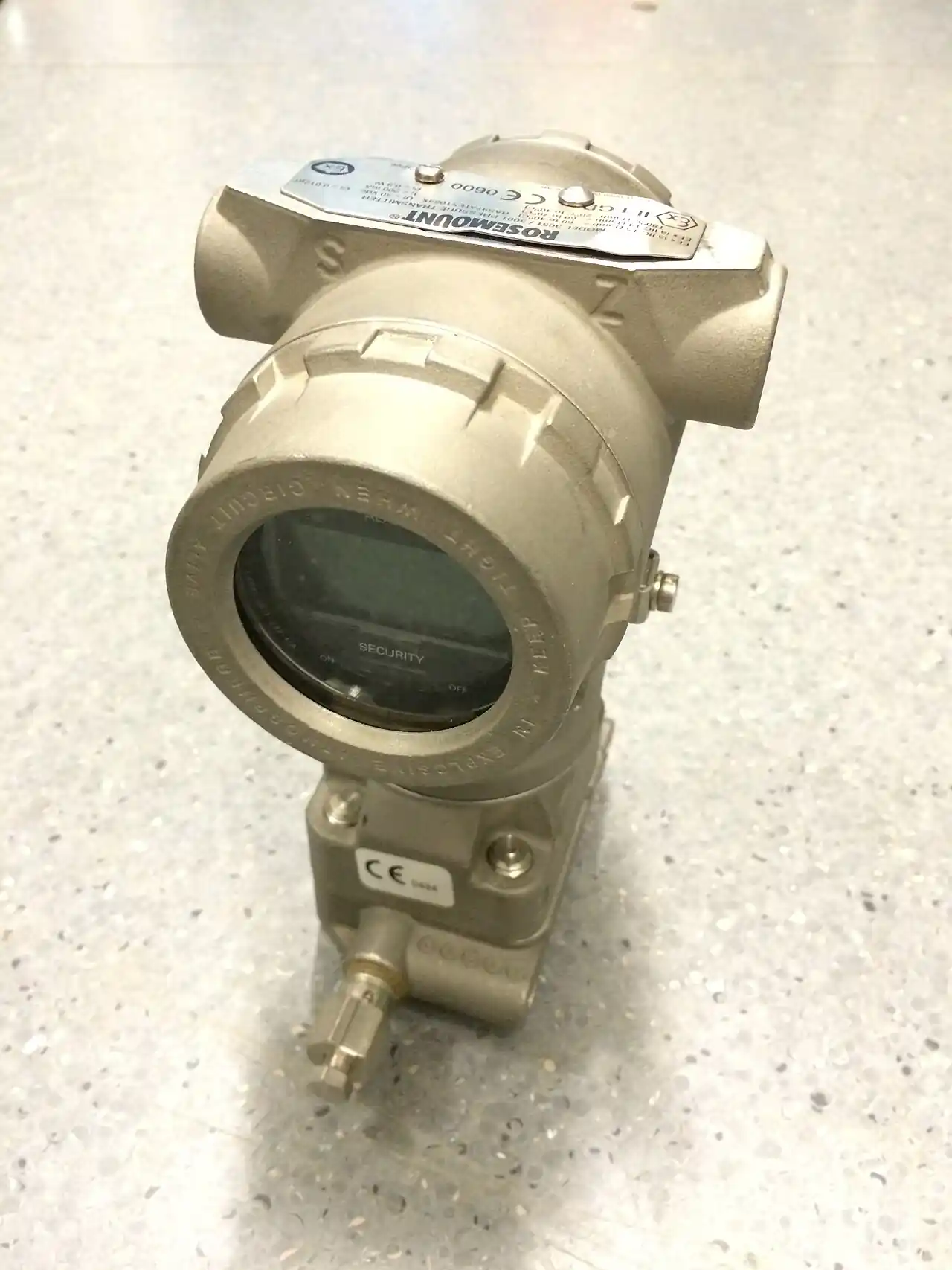
A gauge pressure transmitter measures process pressure relative to the local atmosphere and reports it as a scaled 4 to 20 mA signal, most often with a HART 7 digital channel riding on the same pair of wires. The reference side of the sensing cell is vented to atmosphere through a protected path in the housing, so the output sits at 4 mA whenever both sides of the sensor see the same atmospheric pressure. Readings therefore match the barg and psig values printed on piping drawings, datasheets, and hydrotest records, which is why gauge reference is the default for the majority of plant pressure loops.
The instrument belongs to a three member family, and the reference choice is the first decision on every measurement point. An absolute pressure transmitter seals its reference against hard vacuum, which is the right answer below atmosphere: vacuum columns, condensers, compressor suction guarding, and gas work quoted in absolute units. A differential pressure transmitter carries two live process ports and exists for orifice flow measurement, level in pressurized vessels, and filter condition monitoring. This page is the gauge reference leaf of that family: one live port, one vented port, and an output proportional to the difference between the process and the sky outside the cabinet.
For a specifier the decision set is compact but consequential: range and span, accuracy class, wetted materials, output protocol, and hazardous area approvals. Each choice moves price, lead time, and the calibration calendar. The six chapters below decode the datasheet line by line, explain the sensing physics with the numbers a catalog actually carries, map the duty boundaries where a standard cell must be derated or re-engineered with seals and capillaries, and close with the installation and calibration practice that decides whether a well chosen cell still reads true after two years on the pipe.
This page decodes the gauge pressure transmitter the way a specifier reads it: sensing cell options, span and turndown arithmetic, wetted material limits, signal protocols with wiring consequences, real cost structure, and the field practice that keeps a good cell honest from commissioning through the third calibration cycle.
Chapter 1 / 06
What Is a Gauge Pressure Transmitter?
The measured quantity
Gauge pressure is the difference between absolute process pressure and local atmospheric pressure: p(gauge) equals p(absolute) minus p(atmosphere). At sea level the atmosphere presses at about 101.325 kPa, but the actual figure swings between roughly 97 and 104 kPa with weather and altitude. A gauge transmitter subtracts that moving reference automatically by venting the low side of the cell, so the instrument reads 0 kPa with the process open to air, regardless of whether the plant sits at sea level or 1,800 m up a mesa. That self canceling behavior is the entire point of the reference choice.
The output chain is standardized. A two wire loop powers the transmitter at 24 V DC and carries the measurement as a proportional current: 4 mA at the lower range value, 20 mA at the upper range value, with pressure mapped linearly between them. A living zero at 4 mA lets the host distinguish a true zero reading from a broken wire or a dead loop, which is one reason current loops, not voltage signals, dominate process plants. The same pair can also carry digital data, which Chapter 4 treats as a protocol decision rather than an afterthought.
Gauge, absolute, and differential: picking the reference
The reference choice is made once per measurement point, and it is usually obvious from the process. Above atmosphere, with pressures quoted in barg or psig, the gauge instrument matches every drawing, every pressure gauge on the skid, and every acceptance record already in the file. Deep sub-atmospheric duty is where the absolute pressure transmitter earns its price: a vacuum column running at 25 kPa absolute would show a daily wobble of 2 to 3 kPa on a vented sensor as weather fronts pass, several percent of the reading, while the sealed reference ignores the weather entirely.
The differential pressure transmitter is the third sibling and the busiest of the three. It compares two live process ports: across an orifice plate or venturi to compute flow, from the bottom to the top of a pressurized vessel to infer level, or across a filter housing to time cartridge changes. In flow duty the primary element and the differential cell together form the flow meter of record for the loop. Its two port architecture, three-valve manifold hardware, and equalizing practice are close cousins to gauge installation technique, which is why Chapter 6 borrows from them freely.
When the selection question arises
The gauge transmitter question shows up in three situations. First, a new skid or line needs pressure into the control system, typically one transmitter per pump discharge, header, and vessel. Second, a plant replaces local mechanical indication with signal: a field of dial instruments becomes a wired network feeding the DCS, adding trending, alarms, and history that a bourdon tube cannot hold. Third, an aging loop is upgraded: a purely mechanical pressure switch trip becomes a transmitter plus a software limit, buying adjustable setpoints and pre-alarm bands without touching the process piping.
The comparison with a switch deserves one line of honesty. A pressure switch is cheaper, simpler, and fully satisfies a trip function, but it reports one bit of information. A transmitter reports continuously, supports a PID controller acting on the measured value, and lets operations see a pump walking up its curve hours before an alarm sounds. Most plants end up with both: a transmitter for control and indication, and an independent switch or relief valve for protection, deliberately on separate taps so one plugged impulse line cannot blind both.
What you are actually deciding
Five decisions consume nearly all of the engineering time and all of the schedule risk. Range: the upper range limit and the calibrated span, sized so normal operation sits between 25 and 75 percent of span. Accuracy: 0.075 percent of span is the standard class, 0.04 percent is premium, and most loops do not need premium. Wetted parts: 316L stainless covers the majority of duties, and alloy C-276 covers sour and hot chloride service. Signal: plain 4 to 20 mA, HART 7, or a fieldbus, decided by the host and the maintenance bench. Approvals: the area classification drives Ex d or Ex ia construction. The rest of this page works each decision in turn.
Chapter 2 / 06
Working Principle and Sensing Types
The piezoresistive oil-filled cell
The dominant architecture isolates the sensing element from the process with a thin metal diaphragm and a hydraulic link. Process pressure deflects a corrosion resistant diaphragm by a few hundredths of a millimeter, and incompressible fill fluid, almost always silicone oil, carries that deflection to a silicon chip etched with piezoresistors. The resistors are wired into a Wheatstone bridge, so diaphragm strain arrives as a small differential voltage, on the order of tens of millivolts at full span. The transmitter electronics amplify that signal, digitize it, linearize it against factory characterization, and temperature compensate it before driving the loop.
The oil fill buys three things. Chemical isolation: only the diaphragm sees the process, so the silicon chip never meets sour gas, chlorides, or slurry. Overload protection: a stop behind the diaphragm limits travel when the process spikes, letting the cell survive 2 to 3 times its upper range limit without measurable permanent shift. Manufacturing economy: one silicon design, tuned by fill volume and diaphragm thickness, covers a family of spans from kilopascals to tens of megapascals, which is why the oil-filled piezoresistive cell is the volume leader across every major catalog.
Capacitance and bonded strain gauge alternatives
Capacitance cells place a conductive diaphragm between fixed plates and measure the capacitance shift as it moves. They excel at low spans, down to a few hundred pascals, with strong linearity and low hysteresis, which is why the low span members of differential families often use them. Against piezoresistive parts they give up some shock tolerance and add internal mass, and for gauge spans above roughly 1 MPa they hold no clear advantage, so they appear less often on this page's duty.
Bonded foil strain gauges, resistive elements bonded to the back of a machined stainless diaphragm, are the older and cheaper route, and they still ship in economy industrial transmitters at 0.2 to 0.5 percent of span accuracy. Creep in the adhesive and the bonded layers shows up as long term drift, so the calibration calendar matters more for these cells. For a utility air header read once a day, that can be a fair trade; for a reactor or custody loop it is false economy, because recalibration labor swamps the purchase saving within two cycles.
When a catalog says piezoresistive without further detail, expect the oil isolated silicon cell. A pressure sensor built that way, in a compact stainless body with a small amplifier and a voltage or current output, is also the architecture behind the large mid market of compact units. The pressure transmitter differs from a bare sensor mainly in the electronics: configurable range, damping, self diagnostics, and a loop compliant output, packaged in a housing rated for the plant environment and the area classification.
Span, turndown, and the arithmetic of range setting
Range families are built around a sensor with a fixed upper range limit, then calibrated to whatever smaller span the application needs. A family rated at 100:1 turndown with a 0 to 25 MPa cell accepts calibrated spans down to 0 to 250 kPa. Setting range 0 to 1 MPa on the 0 to 25 MPa cell is a 25:1 turndown, comfortably inside the family but far enough in that the turndown terms in the error budget are no longer negligible.
Do the arithmetic explicitly. Reference accuracy of 0.075 percent of a 1 MPa span is plus or minus 0.75 kPa, which is excellent for most duties. But the datasheet adds a turndown effect and a zero stability term that grow as the calibrated span shrinks against the sensor limit; at 25:1, a realistic total performance is 0.1 to 0.2 percent of span, so plus or minus 1 to 2 kPa. Two rules fall out. Buy the smallest upper range limit that still covers your maximum pressure. And do not burn turndown for convenience, because each halving of span past about 10:1 costs measurable accuracy.
Digital ranging is free at commissioning. A HART communicator, or the local display option, rewrites the lower and upper range values in minutes without touching hardware. Plants exploit this for spare pooling: a handful of 0 to 25 MPa and 0 to 4 MPa cells, re-ranged on demand, can cover dozens of service points at the documented accuracy cost above. The discipline is to record the configured span and the turndown actually used in the instrument register, because the accuracy budget of a pooled spare is rarely the accuracy budget of the instrument it replaced.
The vent path
The gauge reference lives or dies on a small vent path from the low side cavity of the cell to atmosphere, usually a drilled passage in the housing closed by a vent plug or a breathable membrane. Open, the reading self zeros against the weather. Blocked by paint, an insect, or ice, the cavity seals and the instrument quietly becomes a pseudo absolute device: barometric shifts of 2 to 4 kPa now read as process changes, a drift that arrives with the weather map rather than with the process. Chapter 6 puts vent checking on the maintenance calendar for exactly this reason.
From sensor to signal
Inside the electronics, the bridge signal is amplified and digitized at 16 to 24 bits, corrected against an on-board temperature sensor using coefficients established at the factory, linearized, and damped with an adjustable time constant from near zero to tens of seconds, then converted back to current for the loop. Damping deserves attention: one second of damping smooths compressor discharge ripple nicely, while 30 seconds of damping on a trip input will hide a real excursion until after the fact. HART 7 superimposes 1200 baud FSK data on the same pair without disturbing the analog value, and it needs a minimum loop resistance near 230 ohms to develop the signal, a detail that matters when barrier and input card resistances are being totaled.
Proof, burst, and the pressure ladder
Catalogs quote a ladder of pressure limits, and misreading it causes the classic selection failure. Maximum working pressure is what the cell may see continuously, typically equal to the upper range limit. Proof pressure, commonly 2 to 3 times the upper range limit, is a temporary excursion the cell takes without permanent output shift beyond its accuracy band. Burst pressure, commonly 3 to 5 times the limit, is the structural failure envelope at reference temperature. A pump that can deadhead to 9 MPa against a 0 to 4 MPa cell sits above proof on paper: the correct answers are a higher range cell, a relief path, or an overpressure rated seal system, not optimism and a heavy damping setting.
Chapter 3 / 06
Construction, Wetted Materials, and Duty Boundaries
Anatomy of the transmitter
A conventional two compartment transmitter separates the process from the wiring. On the process side sit the connection, usually 1/2 NPT or G1/2, the cell body carrying the isolation diaphragm and fill fluid, and the sensing module. The cast aluminum or 316 stainless housing keeps the amplifier compartment and the terminal compartment apart, so opening the electrical cover does not expose the cell side. An optional local display clips onto the terminal side and shows engineering units, loop current, and diagnostic codes where the technician actually stands. Everything on the wetted path is a corrosion decision; everything after it is an electrical one.
Wetted materials and where they stop
316L stainless is the default diaphragm and body material and covers water, steam, air, most hydrocarbons, and mild chemicals. It has two documented weaknesses. Warm chloride bearing brine above roughly 60 deg C attacks 316L with pitting and stress corrosion cracking. Wet hydrogen sulfide service is governed by NACE MR0175 / ISO 15156 material practice, and the routine answer is alloy C-276 diaphragms and wetted bodies. C-276 tolerates the sour and hot chloride envelope comfortably and typically adds 30 to 60 percent to the wetted parts cost; beyond C-276, tantalum liners and gold overlays handle aggressive chemical service, almost always built as remote seals rather than inline cells.
Hydrogen deserves a specific paragraph because it defeats simple stainless logic. Atomic hydrogen permeates thin diaphragms, dissolves into silicone fill fluid, and recombines as bubbles that shift the zero over days to weeks. Hydrogen duty is specified with gold plated or gold plated C-276 diaphragms and a fill fluid chosen for low permeation. It is an order code decision made when the instrument is bought, never a field retrofit, and a cell that has already soaked in hydrogen is a candidate for replacement rather than recalibration.
Fill fluid selection
The fill fluid is a quiet specification line with real consequences. Standard silicone oil spans about -40 to +120 deg C at the cell and suits nearly everything except strong oxidizers. Oxygen and wet chlorine service prohibit silicone, whose behavior in pure oxygen is a documented hazard, so those duties specify inert halocarbon fill together with cleaning and paperwork for oxygen service. High temperature silicone variants push the working ceiling toward 200 deg C for steam and hot oil, at some cost at the cold end of the range. The wrong fluid is not a nuisance: it is a reorder with the measurement loop down in the meantime.
Process connections
The connection list is short and standard driven: 1/2-14 NPT per ASME B1.20.1 as the North American default, G1/2 per ISO 228 for metric plants, 1/4 NPT on compact low pressure bodies, flanged interfaces per ASME B16.5 in class 150 through 1500 for seal and high pressure work, coplanar and planar modular faces that let one transmitter family share manifolds and seal hardware, and tri-clamp sanitary connections per ASME BPE for food and pharmaceutical lines. Two rules apply. Match the manifold and seal hardware family to the interface. And check that the instrument connection pressure rating, not just the sensor, covers the line rating.
Housings, ingress, and explosion protection
Electrical protection is a matching game between the housing and the area. For ingress, IP66 and IP67 per IEC 60529, or NEMA 4X per NEMA 250, are the working standards for outdoor and washdown mounting, with IP67 adding brief immersion tolerance. For explosion protection, flameproof Ex d per IEC 60079-1 contains an internal ignition inside a certified enclosure and demands certified cable glands. Intrinsic safety Ex ia per IEC 60079-11 limits loop energy below ignition thresholds and demands barriers and IS wiring discipline. Dust ignition protection Ex tb covers zone 21 and 22 powder handling. Enclosure material follows the site: low copper aluminum alloys are the economical Ex d choice, while 316 stainless wins offshore and on chloride laden coastal sites.
Duty boundaries: pulsation, heat, and clogging
Three process conditions retire standard installs, and each has a standard countermeasure. Pulsation from reciprocating pumps and compressors fatigues diaphragms and rattles the output; a piston or porous snubber at the tap, or a needle valve cracked open a quarter turn, drops the amplitude reaching the cell, while electronic damping only hides the ripple from the operator. Heat: above about 120 deg C at the diaphragm, standard silicone fill degrades and the cell drifts; steam duties take a pigtail siphon kept full of condensate, and hot duties take a standoff or up to 5 m of capillary to a transmitter mounted away from the source. Clogging: crystallizing, polymerizing, and solids bearing fluids do not belong on a narrow NPT port at all; a flush diaphragm seal on a flange, connected by capillary, moves the measurement to a wetted surface that sheds rather than traps media, at the price of fill fluid temperature effects on zero that Chapter 6 quantifies.
Chapter 4 / 06
Key Specification Parameters
A pressure transmitter datasheet is a decode exercise: every line either sizes the cell, prices the loop, or sets the calibration calendar. The table below lists the ten lines that decide a gauge transmitter selection, with the catalog spread to expect across mainstream manufacturers and the selection consequence of each. The paragraphs after it work the three lines most often misread: accuracy, turndown, and drift.
Datasheet line
Typical catalog spread
What it decides
Upper range limit (URL)
0.1 to 70 MPa across mainstream gauge families
Sensor ceiling; pick the lowest family that covers maximum process pressure
Calibrated span and turndown
100:1 of URL typical, set at order or by communicator
Working resolution and overrange headroom
Reference accuracy
0.075% of span standard; 0.04% premium
Baseline loop error budget
Long term drift
+/-0.1 to +/-0.25% of URL per year
Calibration interval arithmetic
Proof and burst pressure
proof 2 to 3 x URL; burst 3 to 5 x URL
Margin against deadhead, valve slam, hydrotest
Process temperature at the diaphragm
-40 to +120 deg C with silicone fill
Need for siphon, standoff, or capillary
Ambient temperature limits
-40 to +85 deg C; displays from about -20 deg C
Outdoor mounting, sun load, winterization
Wetted parts
316L standard; C-276 sour; gold plated for hydrogen
Corrosion and permeation duty
Output and protocol
4 to 20 mA; HART 7; FOUNDATION fieldbus; PROFIBUS PA
Host integration and diagnostics depth
Enclosure and approvals
IP66/IP67; NEMA 4X; Ex d; Ex ia
Area classification fit
Accuracy: percent of what, at what span
Accuracy quoted as a percent is meaningless until you ask percent of what. A 0.075 percent of span class on a 0 to 1 MPa calibrated span is plus or minus 0.75 kPa anywhere on the scale, because span referenced error is flat across the range. The 0.04 percent premium class cuts that to plus or minus 0.4 kPa, which matters only if the loop actually uses the band: a pump discharge alarm at 800 kPa plus or minus 10 does not. Pay for premium accuracy on custody transfer, tight ratio control, and safety relevant measurement, and spend the difference on manifolds and calibration discipline instead.
Turndown: the family rating is not free performance
The composite error after configuring a 100:1 rated cell at high turndown includes reference accuracy plus turndown effect plus zero stability over time, and each term grows as the configured span shrinks against the sensor limit. Practical guidance consistent with mainstream catalogs: stay at or below 10:1 when the measurement matters, treat 25:1 as the working limit for control loops, and reserve 100:1 for spare pooling and non critical indication. Wherever the configured turndown exceeds 10:1, commission with a two point verification and record the configured span in the instrument register.
Drift: the line that sizes the calendar
Drift, quoted as a percent of upper range limit per year, decides the calibration interval. Standard cells drift 0.1 to 0.25 percent of URL per year in the mainstream spread, so a 0.15 percent cell over a 25 MPa limit can accumulate tens of kilopascals of potential shift over a multi year interval, which is exactly why the 12 month default exists. Premium families publish combined long term stability figures an order better, which is what makes 3 to 5 year verification defensible outside regulated duties. Buy the drift figure you are willing to verify, not the one that reads best in the brochure.
Reference comparison at a glance
Before protocol, one comparison settles the most common early question: which reference does this point need? The table places the three siblings side by side on the attributes a specifier checks, including the signature symptom that appears when the wrong reference is installed.
Attribute
Gauge reference
Absolute reference
Differential reference
Zero datum
Local atmospheric pressure
Hard vacuum, 0 Pa absolute
High side minus low side
Reading with process open to air
0
approx. 101.3 kPa at sea level
0 with ports tied
Reference implementation
Vent path through the housing
Sealed vacuum cavity
Second live process port
Typical duties
Pump discharge, air headers, steam lines, vessel blanket pressure
Orifice and venturi flow, closed vessel level, filter drop
Typical span examples
0 to 0.25, 0 to 2.5, 0 to 25 MPa
0 to 100 kPa abs, 0 to 2.5 MPa abs
0 to 2.5 kPa, 0 to 100 kPa
Signature misapplication symptom
Clipped negative readings on vacuum duty; weather wobble when the vent plugs
A constant approx. 101 kPa offset against gauge drawings
Frozen output when one leg plugs; zero jumps from manifold mishandling
Hardware consequence
Vent path to protect and inspect
Sealed construction, no vent maintenance
Two ports, three-valve manifold, equalizing practice
Signal protocol options
Protocol choice locks wiring, cabinet hardware, and the maintenance toolset for the life of the plant, so it deserves a decision, not a habit. The table maps the five options a gauge transmitter catalog actually offers against the constraints that bite during design and commissioning.
Protocol
Physical layer and wiring
Reach
Hazardous area practice
What the host gets
4 to 20 mA
Two wire current loop, 24 V DC supply, shielded pair
1 km typical on 1.5 mm2 conductors
Ex ia via barriers or isolators; Ex d with certified glands
One analog value; broken wire detection at 0 mA
HART 7
Same pair plus 1200 baud FSK digital
Same as the analog loop
Same protection concepts; loop resistance near 230 ohms minimum for signaling
Multiple variables per segment; control in the field
PROFIBUS PA
MBP physical layer, 31.25 kbit/s, two wire
1.9 km trunk with repeaters
FISCO and entity models
Cyclic process value plus acyclic parameters
IO-Link
Point to point 24 V, 3 wire, COM3 at 230.4 kbaud
20 m standard cable
General purpose areas; intrinsically safe variants are the exception
Process value plus parameters, identification, simplified replacement
On the host side, a 16 bit PLC analog input card resolves a 20 mA span into steps of about 0.3 microamp, roughly 0.002 percent of span, so the card is rarely the bottleneck; grounding, cable routing, and barrier quality usually are. Whether the PID controller executes in the PLC, in the DCS, or in a single loop controller in the field, the transmitter's job is identical: hold a linear, damped, trustworthy measurement so the control action stays sane. Fieldbus pays where segment infrastructure already exists or where device density makes home run wiring expensive; otherwise HART 7 over 4 to 20 mA is the default that every maintenance technician in the plant can already service.
Chapter 5 / 06
Selection Decision Factors
Selection is a sequence, not a checklist race: each step prunes the option space for the next, and the order below stops the two classic mistakes, sizing span before overpressure and choosing alloys before chemistry. Work it top to bottom and the RFQ writes itself at the end.
Fix the span from the process, not the catalog. Size the calibrated span so normal operating pressure sits between 25 and 75 percent of span: enough headroom that excursions stay on scale, enough working band that control and trending use real resolution. A pump that walks between 600 and 900 kPa takes a 0 to 1.6 MPa span happily and wastes a 0 to 25 MPa cell.
List the overpressure events before the vendor does. Pump deadhead, valve slam, thermal expansion of a blocked liquid line, and hydrotest residue all reach the cell. Every credible event must sit below proof pressure, 2 to 3 times the upper range limit on mainstream cells. Anything above proof is a redesign input, not a tolerance.
Match wetted parts to the chemistry, temperature, and standards file. 316L by default; alloy C-276 for wet sour gas per NACE MR0175 practice and for warm chlorides; gold plated diaphragms where hydrogen permeates; inert fill with oxygen cleaning for oxidizer duty. Write the fluid in the RFQ, not just the alloy, and let vendors propose against it.
Distance the cell from heat. Above about 120 deg C at the diaphragm, budget a siphon, a standoff, or up to 5 m of capillary, and verify ratings at the cold end too: continental outdoor sites see -40 deg C ambient, and displays blank well before the electronics quit.
Let the area classification drive the enclosure concept. Ex d housings want certified glands and conduit practice; Ex ia loops want barriers and disciplined IS wiring. Put the certificate number in the purchase line, not the words explosion proof.
Choose protocol for the host and the maintenance bench, in that order. Plain 4 to 20 mA for simple indication into a PLC analog card; HART 7 as the mainstream default because ranging and diagnostics pay for themselves at first commissioning; fieldbus where the segment already exists.
Set the drift and diagnostics expectation that sizes the maintenance calendar. Premium stability claims support 3 to 5 year verification; standard cells want 12 months. Ask what device diagnostics are available on your protocol: plugged impulse line detection is now a mainstream software option on HART and fieldbus hosts.
Steps 1 and 2 interact: raising the span for overpressure headroom trades away working resolution, and the conflict is real whenever a pump can deadhead far above its normal discharge. Where it bites, the resolution is hardware rather than compromise: a cell with a higher proof rating, a snubber for slam, or a relief path protects the instrument while keeping the span honest. Buying a 0 to 25 MPa cell to survive a 9 MPa deadhead on a 900 kPa duty throws away eleven counts of resolution for every hundred used.
Budget structure is stable across the market. Purchase price is half the story; accessories and recurring calibration are the other half, and the cheapest transmitter on the quote is rarely the cheapest loop at year five. The table below gives planning ranges in US dollars for the variants and the recurring items a gauge loop actually carries.
Cost element
Typical range, USD
What drives the number
Basic 4 to 20 mA gauge transmitter, general purpose
350 to 900
316L wetted parts, IP65 housing, factory or locally set span
HART 7 with Ex d or Ex ia approval
900 to 2,200
Stainless or low copper housing, IP67, ATEX/IECEx certificate scope
High accuracy premium class, 0.04% of span
2,000 to 4,500
Top grade sensing module, documented long term stability, wide composite range
Remote diaphragm seal with 3 to 5 m capillary
adds 800 to 2,500
Seal alloy and size, fill fluid type, capillary length and armor
Accessories: siphon, snubber, block or manifold valves
100 to 600 per set
Alloy and pressure class; three-valve manifolds belong to differential duty
Recurring calibration per transmitter per event
150 to 500
Interval of 12 to 24 months; ISO/IEC 17025 scope and shutdown access
Write the RFQ so vendors quote against measurable lines rather than a model number. A complete gauge transmitter inquiry contains the following eight items, and each one eliminates a class of misquotation on its own.
Fluid and phase: liquid, gas, steam, or slurry, with the chemistry that drives wetted parts, including chloride and hydrogen sulfide content.
Normal and maximum operating pressure with units, plus the credible overpressure event and its magnitude.
Process temperature at the tap, and ambient extremes at the mounting point.
Connection size and type: 1/2 NPT, G1/2, or flange class and face, plus manifold, siphon, or seal intent.
Signal and protocol: 4 to 20 mA, HART 7, or fieldbus, with the host system named.
Area classification: zone or division, gas group, temperature class, and the protection concept preferred.
Accuracy target as a percent of calibrated span, with the reference conditions assumed.
Verification requirement: calibration certificate scope, ISO/IEC 17025 accreditation if the QA file needs it, and the requested interval.
A vendor answering that list has no room to quote a general purpose cell against a sour service duty, and you have no room to be surprised by an accessory line at month two. The checklist is deliberately short enough to attach to a purchase requisition, which is where selection discipline actually survives contact with procurement.
Chapter 6 / 06
Field Practice: Installation, Calibration, and Failure Modes
Impulse piping orientation
Orientation follows the fluid. In gas service, tap the top of the pipe and mount the transmitter above the tap, so condensate drains back to the process instead of collecting a hydraulic head on the cell. In liquid service, tap the side of the pipe and mount the transmitter at or below the tap, with lines flooded solid and vented at commissioning. In steam service, a siphon or condensate loop sits between tap and instrument and must stay full, because live steam reaching a silicone filled cell is a fill fluid failure, not a reading error.
Every vertical meter of liquid leg is a standing head error of about 10 kPa for water, more for dense fluids, and it is compensable at zero trim only if the leg holds a constant height and density. That is the quiet argument for close coupling: a compact transmitter mounted directly on the tap deletes the leg, the head arithmetic, and a winterization problem in one stroke, at the price of vibration exposure that supports and snubbers must then manage. Where the tap must be remote, keep lines short, sloped, and labeled with the head correction that was applied.
Valves and manifolds
Isolation practice on gauge duty is a block valve or a block and bleed combination sized to the connection. The three-valve manifold belongs to differential duty, where isolating and equalizing two ports without opening either to atmosphere is the whole game; on a gauge point its equalize valve does nothing, though plants often standardize the hardware anyway for spares and training. Whatever the arrangement, rate the valve train to the line, not to the sensor: a class 150 manifold on a class 300 line is an audit finding with a date already on it.
Zero trim and loop checkout
The commissioning sequence that survives audits is short. With the loop powered and stable, vent the cell to atmosphere and confirm that both the local display and the host read zero, then apply a zero trim. Next, apply a known pressure near 75 percent of span from a pressure calibrator, confirm the reported value against the applied value, and trim or re-range only if the deviation exceeds the loop budget. Record as-found and as-left at every point: the trend across calibrations is the real drift record, and it is the evidence that justifies stretching or shrinking the interval later.
The electrical half of the checkout mirrors the procedure used on any temperature transmitter: verify 4 mA at live zero, drive 20 mA at full span, confirm the PLC analog input reading against the local display, and log loop resistance and supply voltage at the transmitter terminals. Test terminals on the transmitter let a technician insert a milliammeter without breaking the loop; use them, because the loop you break to take a measurement is the outage you explain afterwards. Bond the housing to the local structure ground, land the cable shield at the cabinet end only, and keep the 24 V return grounded at one point.
Grounding and surge discipline close the electrical list. Split grounding paths on long runs are the classic invisible noise source, arriving as a wobble that no damping setting cures, and lightning season on exposed runs between buildings accounts for a steady share of so-called sensor failures. A surge protector at the cabinet boundary is cheap insurance against both, and a quarterly glance at the trend history catches the rest early.
Calibration intervals and drift management
Default intervals: 12 months for standard duty, 6 months where the measurement feeds custody transfer or fuel gas accounting, and 24 to 36 months defensible for premium cells with documented long term stability outside regulated duty. Set the interval from as-found history, not from the vendor's calendar: two consecutive as-found results inside the loop budget justify stretching the interval, and one outside justifies halving it. Every verification must state the calibrator class, because a field standard at 0.05 percent of reading cannot audit a transmitter claiming 0.04 percent of span; when the numbers are that close, the lab and the fixture decide, not the field kit.
Failure modes and how to specify against them
Plugged impulse leg. Response slows first, then the reading freezes while the process moves on. Specify larger bore tubing on fouling service, slope lines so they self flush, and put the point on a routine exercise list; on supported digital protocols, plugged leg detection alarms on the signature change.
Fill fluid loss through a pinholed diaphragm. The output drifts and grows noisy as the hydraulic link ingests gas. Specify the diaphragm alloy for the chemistry at order, inspect the diaphragm at every calibration, and treat unexplained zero shift on a corrosive duty as a seal investigation, not a trim.
Vent blockage. The transmitter quietly becomes quasi absolute and tracks the weather, reading 1 to 3 kPa low as a low pressure front passes. Keep the vent plug paint free and clear, check it at every calibration, and prefer housings with a protected vent path on washdown and outdoor sites.
Overpressure. Deadhead or water hammer above proof leaves a permanent zero shift that shows up later as an as-found step change. Compare every credible transient against the proof ladder at selection, and fit snubbers where slam is routine.
Temperature induced zero shift on capillary systems. Fill fluid expands with ambient cycles, moving the zero by the equivalent of a few kilopascals per 10 deg C on long capillaries. Route capillaries out of direct sun and away from steam traces, insulate where the swings are large, and record the installation temperature at commissioning.
Electronics and power. Switching supply ripple on the 24 V bus and moisture in poorly glanded housings account for a steady share of failures booked against the sensor. Gland to the actual cable diameter, torque covers to the housing spec, and verify loop voltage at the transmitter terminals at commissioning.
Maintenance calendar
A defensible annual list is short: clean and verify the vent path, exercise the isolation valves, inspect diaphragms and gaskets, replace soft parts on the schedule the chemistry dictates, verify as-found against a traceable pressure calibrator, trim to as-left, and file both numbers. Gasket and O-ring replacement at every calibration is cheap insurance against the slow leak that otherwise announces itself as a month long drift investigation. Between calibrations, the best maintenance is observation: a trend that wanders with the weather says vent, a trend that steps says process event, and a trend that ramps says fill fluid or chemistry, and each verdict sends a technician to a different paragraph of this chapter.
FAQ
When do I need a gauge reference versus an absolute reference?
Choose gauge whenever pressures are quoted relative to atmosphere and the process sits above it: pump discharge, air headers, steam and utility lines. Choose absolute when the operating pressure is at or below atmosphere, for example a vacuum column at 25 kPa absolute, where daily barometric swings of 2 to 3 kPa would be several percent of the reading. As a rule of thumb, below roughly 0.1 MPa absolute, or wherever barometric variation is a large fraction of the span, buy the sealed reference.
What accuracy do I lose calibrating a 0 to 25 MPa cell down to 0 to 1 MPa?
That configuration is a 25:1 turndown, inside a 100:1 rated family but deep enough that the turndown terms matter. Reference accuracy of 0.075 percent of the 1 MPa span is plus or minus 0.75 kPa, and a realistic field total at 25:1 is 0.1 to 0.2 percent of span, so plus or minus 1 to 2 kPa. Resolution improves over a 0 to 25 MPa span, but plan a two point verification at commissioning and a firmer zero check cadence.
Can a standard gauge transmitter be recertified for hydrogen service?
No. Recertification verifies the instrument as built; it cannot change metallurgy. Atomic hydrogen permeates thin 316L diaphragms and dissolves into silicone fill fluid, producing zero drift that recalibration will chase but never remove. Hydrogen duty is an order code decision: gold plated or gold plated C-276 diaphragms with fill fluid selected for low permeation. A standard cell with months of hydrogen exposure is a replacement, and it should come out of the loop before its drift misleads the operation.
What accuracy is realistic after a field calibration?
Expect plus or minus 0.15 to 0.3 percent of span from a careful field calibration with a temperature compensated pressure calibrator, against the 0.075 percent reference accuracy on paper. Mounting offset, impulse line head, ambient swing, and the calibrator class each add terms. A three point as-found and as-left run at 0, 50, and 100 percent of span documents the band actually achieved. Better than 0.1 percent of span generally needs a laboratory, a fixture, and a temperature soak.
How far can the transmitter sit from the process tap?
A working limit is about 15 m of impulse line in liquid service and 30 m in clean dry gas, using 9 to 12 mm tubing. Longer runs add transport lag and temperature driven density error: every vertical meter of water filled leg is about 10 kPa of head. Steam needs a full condensate siphon at any distance. Beyond these limits, or on clogging and hot media, move to a flush seal with capillary and accept its thermal zero effects.
What causes a gauge transmitter to drift with the seasons?
Check the vent first. A vent blocked by paint, an insect screen, or ice seals the reference cavity and turns the transmitter into a quasi absolute instrument that tracks weather fronts, reading 1 to 3 kPa low as low pressure passes. Second candidates are fill fluid expansion in unshaded capillary runs and ambient cycles on long impulse lines. Cleaning the vent path and re-zeroing against atmosphere resolves most weather correlated drift without touching the calibration itself.
Are Ex d and Ex ia installations interchangeable on one loop?
No, they are different protection concepts, not labels. Ex d contains an internal ignition inside a flameproof enclosure and depends on certified glands and flamepaths. Ex ia limits electrical energy below ignition thresholds and depends on barriers and intrinsically safe wiring. Swapping concepts means redesigning the loop: a different enclosure, different glands, and new energy calculations. Both can hold ATEX and IECEx certificates, and one transmitter family often offers both, but a single loop follows a single concept.