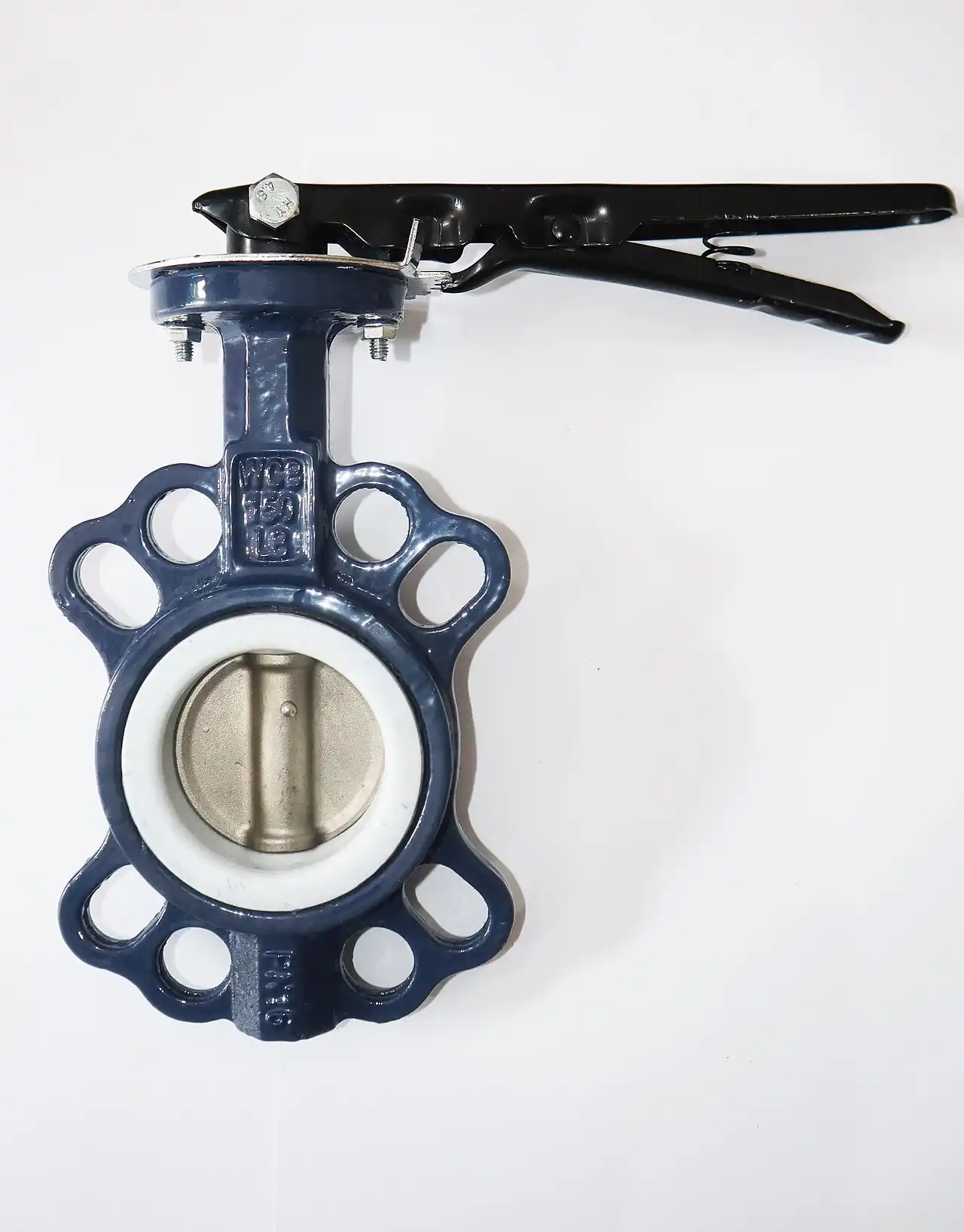
A lug butterfly valve is a quarter-turn isolating valve whose body carries tapped ears that accept flange bolts from either side. Those ears are the entire difference from a wafer butterfly valve, and they change what the assembly can do: because each pipe flange bolts to the valve body itself, one joint can be broken and the downstream piping removed while the upstream side stays pressurized, with the closed disc holding the line as an end-of-line valve. That single capability drives most lug versus wafer decisions on water, HVAC, and utility projects.
This page treats the lug butterfly valve as a specification problem, not a catalog scan. It covers what the lug body buys and what it costs in dollars and torque, how a resilient seat actually seals and how the torque profile builds through the 90 degree stroke, where EPDM, NBR, PTFE, and FKM seats stop being suitable, how to decode each datasheet line from nominal size down to flange drilling, and how to write the RFQ so competing quotes come back comparable. Standards anchors run through every chapter: ASME B16.10 for face-to-face dimensions, ASME B16.34 for class-rated pressure boundaries, API 609 for butterfly valve categories, FCI 70-2 for leakage classification, and ISO 5211 for operator mounting.
The lug body turns a butterfly valve from a sandwiched disc into a self-contained pressure boundary. Specifying it correctly means matching seat compound, disc offset family, pressure class, and operator torque budget to one duty, in that order, and writing each of those lines into the RFQ so suppliers quote the same valve.
Chapter 1 / 06
What Is a Lug Butterfly Valve
Definition and the job the lugs do
Every butterfly valve closes a line by rotating a disc 90 degrees on a stem through the pipe centerline. The lug style is defined by its body: instead of unthreaded through-holes like a wafer valve, the body carries cast ears machined with tapped holes that match the flange bolt pattern, for example eight lugs on a DN100 Class 150 body. Each pipe side bolts independently into those threads, so the valve becomes the structural member between two flanges rather than a spacer squeezed between them.
Two capabilities follow directly. First, dead-end service: with the downstream flange removed, the closed disc and seat hold full line pressure, which most catalogs rate at the full Class 150 or PN16 value for common sizes, with deratings on larger bores. Second, bi-directional shutoff: a concentric resilient seat presses on the disc edge identically from either direction, while many wafer designs carry a preferred flow arrow because the seat is backed on one side only. Wafer valves can stand at a line end only when the manufacturer explicitly extends the rating; the lug body carries it by design.
What is actually being decided when this valve enters a specification is a package of four linked choices: body style (lug, wafer, or double flanged), seat compound, disc offset family, and operator. A change in any one shifts the others. Selecting a PTFE seat, for instance, raises seating torque and can push a DN150 valve from lever to gear operation without any change in duty.
When the lug question arises
The lug body earns its price premium wherever a line may need to be broken, tested, or isolated section by section: riser isolation in high-rise HVAC, pump suction and discharge isolation, treatment train isolation in water plants, and end-of-line connections at tank farms and utility yards. Set beside a gate valve, the butterfly wins on face-to-face length and weight at equal diameter, by a factor of 3 to 5 on DN300 and larger. Set beside a ball valve, it wins on cost and installed envelope, at the price of a disc that always stays in the flow stream and a somewhat higher pressure drop. Neither comparison settles the body-style question, which is why this page starts with the lugs.
Disc offset families and the size window
Concentric resilient-seat valves, the focus of this page, put the disc center on the pipe axis and seal on a molded elastomer seat; they dominate DN50 to DN600 general service. Double offset, or high performance, designs shift the disc both off the pipe axis and off the seat sealing centerline so it swings clear of the seat through most of its travel; they carry metal or layered seats, reach Class 300 and 600, and work to about 200 deg C with suitable seat construction. Triple offset designs add a third geometric offset and a laminated metal seal that cams into position without rubbing, reaching toward 540 deg C with the right body and trim materials. All three families come in lug bodies, so the real selection question is which seat technology the duty demands, followed by the body style that carries it.
Common size coverage runs DN50 to DN600 (NPS 2 to 24) for catalog lug valves in ductile iron, with Class 150 the default rating and Class 300 available in the high performance lines. Beyond DN600 the market shifts to double flanged bodies built to waterworks standards such as AWWA C504, where gear operators and buried service arrangements are standard rather than adders. Pressure class ratings for metal designs trace to ASME B16.34 pressure-temperature tables; resilient seat valves carry manufacturer ratings validated by test, as Chapter 3 details.
Chapter 2 / 06
Working Principle and Seating Behavior
The quarter-turn stroke and seat interference
The disc seals by mechanical interference, not by fluid pressure. The molded seat bore is undersized relative to the disc edge, so at the closed position the disc edge compresses the elastomer by roughly 15 to 25 percent of its section. That squeeze, held by stem torque at closing, produces the bubble-tight shutoff that water and HVAC duties expect; in leakage-class terms a sound resilient seat tests to the intent of FCI 70-2 Class VI, bubble-tight, at rated differential. Reaching full closure is therefore a torque event: the last few degrees of travel spend most of the stem's work squeezing seat rubber, not moving fluid.
Opening reverses the same physics. Break torque at the closed position is the sum of three components: the seat interference torque, which is nearly constant with pressure; the bearing and hub torque, which grows with the pressure load carried by the stem; and the hydrodynamic torque, which flowing fluid applies to the partly open disc. On a DN100 EPDM seat valve, catalog break values cluster around 60 to 90 Nm at 1.0 MPa differential; a DN150 runs 150 to 220 Nm, a DN200 280 to 400 Nm, and a DN300 800 to 1100 Nm under the same differential. These spreads are real between makers, which is why operator sizing must start from the actual valve torque table, never from nominal size alone.
Dynamic torque and the mid-stroke peak
Hydrodynamic torque does not peak at full open, where the disc aligns with the flow, but in mid travel: for a symmetric disc the peak lands near 60 to 75 degrees open, where projected area and local velocity combine to maximum effect. A valve throttling continuously at that angle under high differential feeds energy into the stem and bearings, and a marginally sized operator can stall exactly there. This is also the region where the flow characteristic flattens out: from 70 to 90 degrees open the disc adds little, typically under 10 percent of additional capacity, so an isolation valve parked at 85 degrees gains almost nothing over one at 70.
Flow capacity: Cv and equivalent opening area
Full-open capacity is published as the flow coefficient Cv, and it scales close to pipe area. Typical catalog values for concentric resilient seat valves run approx. 80 at DN50, 200 at DN80, 320 at DN100, 760 at DN150, 1450 at DN200, 2400 at DN250, 3600 at DN300, rising to approx. 15500 at DN600, with plus or minus 15 percent between manufacturers. In equivalent opening area terms, a full disc leaves about 85 to 95 percent of the pipe bore unobstructed; the stem and disc hub account for the remainder. Water flow follows the standard relation: gallons per minute equals Cv times the square root of the pressure drop in psi, so a DN100 at Cv 320 passing 400 gpm drops roughly 1.6 psi fully open. In metric terms, Kv runs about 0.86 times Cv, so the same valve passes 100 m3/h at about 0.13 bar.
For sizing isolation valves, full-open Cv rarely decides anything; line velocity does. Keep continuous water service between 3 and 4.5 m/s and throttling service below about 6 m/s, and the full-open pressure drop of a butterfly stays in the noise. Where Cv matters is turndown: the valve behaves as a control element only between roughly 20 and 70 degrees open, where its installed characteristic approaches equal percentage between 30 and 60 degrees.
Throttling, cavitation, and choking
Below about 20 degrees open the flow path becomes a high-velocity jet over the seat edge; sustained duty there cuts elastomer seats and erodes metal ones. Throttling against high differential also invites cavitation in liquid duty: when local pressure at the disc edge falls below vapor pressure, vapor bubbles form and collapse just downstream, hammering the disc edge and adjacent pipe wall. As a first pass, using a pressure recovery factor near 0.7, expect trouble when the drop across the partly open disc exceeds about half the difference between upstream absolute pressure and liquid vapor pressure, and confirm against the manufacturer's cavitation chart before accepting any deep-throttling assignment. A valve throttling immediately downstream of a centrifugal pump at high differential, with little straight pipe to smooth the approach, is the classic exposure case; the same pump discharge line still needs a check valve, because an isolating butterfly does nothing against reverse flow and reverse rotation.
Choking sets the hard ceiling: once the vena contracta reaches vapor pressure, further opening adds no flow, and the valve simply converts the excess drop into noise, vibration, and erosion. If the duty needs stable control over a wide range, accept that a butterfly is a two-trick element, isolate or coarse-throttle, and put a purpose-built control element on the fine work, for example a globe valve with a characterized plug. In hydronic systems, characterized discs and position indicators let a butterfly serve as an economy balancing valve on small branches, but a dedicated balancing valve with a fixed measurement characteristic remains the instrument of record for commissioning-grade balance.
Chapter 3 / 06
Construction, Materials, and Duty Boundaries
Body and pressure boundary
The workhorse body is ductile iron to ASTM A536 grade 65-45-12, coated inside and out with fusion bonded epoxy at 250 to 400 um, about 10 to 16 mil; potable water service calls for a coating qualified to AWWA C550. Where chloride chemistry, CIP fluids, or food contact rule out iron, the same valve comes in CF8M stainless construction at roughly 1.8 to 2.2 times the iron-body price. The lugs are tapped directly into the ductile iron on standard models; corrosive or high-cycle plants should specify stainless or brass threaded inserts, because stripped lug threads are the most common reason an otherwise sound lug body gets cut out of the line.
Pressure boundary ratings are catalog properties, not derivations. Resilient seat valves carry manufacturer ratings validated by shell testing at about 1.5 times rated pressure and seat testing near 1.1 times, following API 598 or ISO 5208 practice, while class-rated metal designs fall under ASME B16.34 pressure-temperature tables. The number that matters for the lug decision is the dead-end rating, which reputable catalogs publish separately by size; treat any datasheet that does not state it as a wafer-equivalent valve regardless of the body style.
Disc, stem, and bearings
Disc options track the media. Ductile iron with a nylon 11 or 12 coating suits clean water and keeps cost down; 316 or 316L stainless serves chemical, food, and coastal duties; aluminum bronze C95200 earns its price step in seawater and steam condensate. The stem is 416 or 17-4 PH stainless on standard valves and 316 on full stainless builds, running in PTFE-lined or bronze bearings and, on concentric designs, assembled so it cannot blow out under pressure. Stem sealing is layered: the seat itself shields the lower bearing, and a secondary O-ring near the upper bearing zone keeps line fluid out of the running gear. Ask for the stem seal material to be stated on the datasheet, because it is an elastomer choice carrying the same chemical limits as the seat.
Seat compounds and their hard limits
EPDM is the default for water, glycol mixtures, dilute acids, and steam-free hydronic duty, usable from about -34 to +107 deg C continuously with 120 deg C intermittent. It must never see petroleum oils, fuels, or most hydrocarbons, which swell it irreversibly; a single oil-mist lubricated compressed air line is enough to ruin an EPDM seat within months. NBR covers oils, fuels, and ambient duties from -29 to +90 deg C but must not see steam or hot water above its rating, and it weathers poorly in ozone and sunlight, so spares need dark storage. PTFE jackets over an elastomer core buy broad chemical resistance to 200 deg C at the cost of higher seating torque and slower recovery. FKM handles hydrocarbons, many acids, and dry hot air to about 180 deg C but fails in steam, amines, and ketones. The seat decision is a chemistry decision first, which is why Chapter 5 forces it to the front of the selection sequence.
Where each family stops
Concentric resilient seat designs carry practical ceilings near 1.6 to 2.0 MPa and 120 deg C with EPDM, lower with NBR; those are the boundaries of this page's mainstream catalog. High performance double offset designs in lug bodies reach Class 300 and about 200 deg C with graphite or layered seats, and triple offset metal seat designs extend toward 540 deg C with the right body alloy, which is beyond resilient seat physics entirely. Abrasive slurry is a separate boundary: solids load the seat edge and score the disc and stem until the valve will not seal, and no elastomer choice fixes that geometry problem. Slurry duty belongs to a knife gate valve or a lined valve, not to a butterfly disc sweeping its own seat through 90 degrees every cycle.
Two further boundaries deserve a line each. Vacuum and low differential do not trouble a resilient seat, but sustained throttling near closed does, as Chapter 2 showed, and bi-directional claims need the datasheet's own words: concentric resilient seats are inherently symmetric, yet some wafer and offset designs publish direction-dependent leakage classes, so the purchase order should name the required direction of sealing.
Chapter 4 / 06
Key Specification Parameters
A datasheet for a lug butterfly valve compresses every decision from Chapters 1 to 3 into about ten lines. The decode table below reads each line the way a specifier should: what the catalog states, a typical DN100 spread for orientation, and what the line decides downstream of it. Example values describe a ductile iron, EPDM seat, stainless disc valve; your duty moves them.
Datasheet line
Typical DN100 catalog spread
What the line decides
Nominal size
DN50 to DN600 (NPS 2 to 24)
pipe schedule match, face-to-face, operator class
Pressure class
PN10, PN16, Class 150; HP lines Class 300
shell and seat test levels, dead-end holding
Seat material
EPDM, NBR, PTFE, FKM
media chemistry and temperature ceiling
Seat temperature window
EPDM -34 to +107 deg C, 120 intermittent
seasonal minimum and flush or CIP maximum
Disc material
nylon coated ductile, 316, 316L, aluminum bronze
corrosion tier and cost step
Stem and bearings
416 or 316 SS, PTFE or bronze bearings
torque life, corrosion, blowout design
Flow coefficient Cv
approx. 320 full open, 280 to 370 spread
pressure drop at design flow
Torque at max delta P
60 to 90 Nm break at 1.0 MPa
lever, gear, or powered operator
Face-to-face
ASME B16.10 short pattern / ISO 5752
retrofit fit into existing spools
Flange drilling
ANSI B16.1 Class 125, B16.5 Class 150, DIN PN16, JIS 10K
mating with the installed pipe class
Reading pressure and temperature together
Class and seat window are one decision, not two. A Class 150 iron body is comfortable at 1.6 MPa cold, but the EPDM window closes at 107 deg C continuous, and derating curves cut allowable pressure as temperature climbs; by 120 deg C the same catalog may cap a resilient seat at 1.0 MPa or less. Read the pressure-temperature chart for the seat actually quoted, not the body rating, and mark the intersection of your worst-case temperature and worst-case pressure on it before the valve goes on the purchase order.
Reading Cv and torque together
The Cv line sizes the pipe-side story and the torque line sizes the operator-side story. The DN100 example of 60 to 90 Nm break at 1.0 MPa says a lever, practical to about 150 Nm of hand effort, covers DN100 and often DN150; a self-locking gear operator takes over by DN200; and powered operation is standard by DN300, where 800 to 1100 Nm exceeds hand effort regardless of handle length. Both numbers must come from the same manufacturer's table: torque depends on seat compound, disc geometry, and coating, so mixing a Cv from one catalog with a torque from another produces a confidently wrong operator size.
Lug versus wafer, line by line
The body-style comparison below condenses Chapter 1 into the attributes that actually move money and risk. Cost and weight figures are indicative ex-works spreads for DN100 ductile iron with EPDM seat and stainless disc; absolute numbers move with volume and market, the ratios hold.
Attribute
Lug body
Wafer body
Dead-end service
rated to full class on common sizes, check derating above DN250
not rated; line end needs a blind flange
Downstream pipe removal
yes, unbolt the downstream side only
no, through-bolts tie both flanges together
Bi-directional shutoff
standard on concentric resilient seats
often preferred-flow, marked with an arrow
Cost, DN100 example
approx. 45 to 75 USD
approx. 35 to 60 USD
Weight, DN100 example
approx. 8 to 11 kg
approx. 6 to 9 kg
Installation care
bolts thread into lugs, torque capped by the seat
through-bolts demand careful flange alignment
Typical duty
risers, end-of-line, section isolation
mid-line isolation, cost-driven packages
Seat selection matrix
The seat matrix is the most-used reference on this page and the table to attach to the media section of an RFQ. Values are conservative catalog limits; the quoted datasheet for the specific compound governs.
Seat compound
Best media
Temperature window
Hard limits
EPDM
water, glycol mixes, dilute acids, hydronic loops
-34 to +107 deg C, 120 intermittent
no oils, fuels, or hydrocarbons; swells
NBR
oils, fuels, air with oil mist
-29 to +90 deg C
no steam; poor ozone and sunlight aging
PTFE jacketed
strong chemicals, chlorine, solvents
-50 to +200 deg C
higher seating torque, slower recovery
FKM
hydrocarbons, many acids, dry hot air
-18 to +180 deg C
no steam, amines, or ketones
Chapter 5 / 06
Selection Decision Factors
Selection is a sequence, not a checklist of equals. Run it in order and each answer prunes the next question; run it out of order and a cheap valve arrives with the wrong seat. The seven steps below cover single duty valves; package buys add a standardization step at the end.
Media and chemistry. Write the fluid, its solids loading, and its chemical package, including inhibitors and cleaning cycles, before anything else. Every later choice from seat to coating hangs on this line, and hydrocarbon carryover silently deletes EPDM from the option set.
Temperature. State minimum ambient, maximum continuous, and any intermittent flush or CIP peak with its duration, for example 110 deg C for 30 minutes weekly. A seat window is a band, not a single number, and intermittent ratings carry cycle limits.
Pressure class. Fix the maximum differential the closed disc will actually see, not the nominal line pressure, then choose PN10, PN16, or Class 150 against the pressure-temperature chart; step up to a Class 300 high performance line only if temperature or shutoff class demands it.
Shutoff tightness. Resilient seats deliver bubble-tight performance in the intent of FCI 70-2 Class VI; metal high performance seats typically carry Class V, and the difference matters on toxic, expensive, or metered fluids. Name the leakage requirement and its test standard in the RFQ.
Dead-end and removal needs. Decide now whether any operating scenario breaks the downstream flange under pressure. If yes, the lug body is mandatory and the dead-end rating by size must appear on the datasheet; if no, wafer economics apply.
Operator and torque budget. Take break and running torque at your differential from the valve table, add 25 to 30 percent margin, and size the lever, gear, or actuator from that number. This is where a pneumatic valve actuator or an electric quarter-turn operator enters the specification, with its own fail action and control signal lines.
Flange standard and face-to-face. Close with the lines that prevent rework: drilling standard (ANSI B16.1 Class 125, ASME B16.5 Class 150, DIN PN10 or PN16, JIS 5K or 10K), face-to-face per ASME B16.10 or the ISO 5752 short pattern, face type, and coating specification.
Cost structure at DN100
The table breaks indicative ex-works cost by operator configuration at DN100, ductile iron body, EPDM seat, 316 disc. Treat the numbers as a sanity check for quotes, not as prices; volume, origin, and material swings dominate single units. The wafer to lug step is small money; actuation is where the curve bends.
Material steps move the base valve more than the operator does on small sizes: a 316 disc adds roughly 15 to 30 percent over coated ductile, aluminum bronze sits between, and a CF8M all-stainless body lands near double the iron price. Coatings follow a smaller ladder: standard epoxy is included, nylon 11 for buried or severe service adds a modest step, and potable-water qualified coating adds a certification premium rather than a materials one. None of these steps changes the sequence above; they change only where the budget lands.
What to write in the RFQ
Fluid, solids loading in ppm or percent, and the full chemical package including inhibitors.
Minimum and maximum temperature, continuous and intermittent, with cycle duration and frequency.
Maximum differential pressure across the closed disc and its direction or directions.
Dead-end requirement stated explicitly, with the size and pressure it must hold.
Seat, disc, stem, and stem seal materials named, not implied by duty.
Flange drilling standard, face type, and face-to-face standard for retrofit lines.
Operator type, torque budget with stated margin, fail-safe action, and control signal.
Position feedback, tamper switch, and lockout requirements.
Buried or pit service items: stem extension, valve box, corrosion coating.
Test standard and acceptance, for example seat test per ISO 5208 rate A, plus material certification to EN 10204 3.1.
Spare seat kit line items and the quoted seat replacement interval for the stated duty.
Chapter 6 / 06
Field Practice: Installation, Compliance, Failure Modes, and Maintenance
Installation: the seat is the gasket
On a resilient seat valve, the molded elastomer stands proud of the body faces and compresses against the mating flange faces, so the seat does the sealing job of a gasket and no separate gasket is used. That places three demands on installation. The flange faces must be flat, clean, and free of deep tool marks, because the seat prints whatever it seats against. The bolts must be tightened in a cross pattern in three passes, roughly 30, 70, and 100 percent of the specified torque, so the seat compresses evenly and the body does not rack. And the final torque must respect the manufacturer's cap, since an over-torqued flange crushes the seat, drives up break torque, and can crack a ductile body ear; the correct cap is a published number, not a fitter's feel.
Set the disc about 10 degrees open before drawing the flanges together, so the disc edge stays inside the body face planes during handling. On cement-lined or epoxy-lined pipe, check whether the lining stands proud of the flange face; if it does, the valve seat will bear on the lining instead of the flange face and may crush or crack it. Utilities that cannot verify lining face condition sometimes fit a thin full-face elastomer sheet as a compression spacer; that sheet then becomes the sealing gasket and its thickness belongs in the torque calculation. On GRP and other lined systems, follow the pipe maker's torque table whenever it is lower than the valve's published cap.
Orientation, burial, and accessories
Install with the stem horizontal wherever the line allows. A horizontal stem keeps settled solids off the upper bearing and keeps the seat loaded symmetrically as the disc cycles; vertical-stem installations in horizontal pipes work but collect debris on the upper disc half in dirty service. Follow the flow arrow when the datasheet defines one, even on bi-directional models, because the marked direction usually protects the seat edge in throttling. Buried valves take a stem extension and valve box, with the extension material stated for soil chemistry, and gear operators need their drain or breather positioned for the box.
Actuator sizing and commissioning
Size powered operators from the valve torque table at maximum differential, then add a 25 to 30 percent margin on break torque. Undersizing stalls the operator at the mid-stroke torque peak described in Chapter 2; oversizing past the valve's allowable stem torque can crush the seat or twist the stem, so the margin is a band, not a bonus. Mount per ISO 5211 flange and coupling dimensions, set the closed and open travel stops against the seat before applying full torque, and verify the 0 and 90 degree positions under air or power. For a pneumatic valve actuator, state supply pressure at the actuator, not at the compressor room; a 0.55 to 0.7 MPa supply is the common assumption, and every 0.05 MPa lost at the regulator shrinks the output torque envelope. Commissioning should record break torque if the operator reports it, plus a seat leak check at operating pressure.
Failure modes and how to specify against them
Seat swelling or hardening from wrong fluid chemistry, for example EPDM in hydrocarbon carryover. Specify seat and stem seal compounds explicitly and police what the fluid actually carries.
Seat crushing from over-torqued flange bolts. Put the bolt torque cap in the installation spec and require a torque wrench on the record.
Disc and stem scoring in abrasive service. Set a solids limit with the supplier or move the duty to a knife gate valve or a lined valve.
Cavitation erosion from deep throttling at high differential. Spread the drop across two valves, open the disc angle, or add a downstream restriction, and confirm against the maker's cavitation chart.
Stem or operator damage from windmilling in idle lines. Lock the disc or remove the lever during outages on exposed vents and drains.
Ozone and UV cracking of NBR seats and spares in storage. Store valves dark and cool, discs about 10 degrees open, and respect elastomer shelf life, typically 10 to 15 years for EPDM in good conditions.
Maintenance and service intervals
Exercise isolating valves quarterly through at least one full cycle; a seat that has not moved in two years will have taken a set, and the first stroke after a long rest is when stems and operators fail. Inspect gear operators yearly and lubricate per the maker's schedule, more often in washdown or outdoor duty. Plan seat replacement by duty severity rather than calendar alone: clean tempered water at moderate temperature commonly runs 8 to 12 years on the original seat, hot service or high-cycle throttling can halve that, and a 5 year seat kit budget line is the standard conservative planning number. Track break torque over time where the operator reports it; a steady climb is the seat taking a set or swelling before leakage announces it. Keep one spare seat kit per size per duty in critical sections, and log serial numbers and torque readings against each tag number so the replacement interval becomes measured rather than guessed.
For acceptance and periodic testing, reference the standards by name in the purchase order: shell and seat testing to API 598 or ISO 5208 at rated conditions, pressure-temperature compliance for metal designs to ASME B16.34, face-to-face interchangeability to ASME B16.10, and leakage classification to FCI 70-2 where control-grade shutoff is bought. A valve that arrives with test certificates against those named standards installs once; a valve bought on price alone often installs twice.
FAQ
Can a lug butterfly valve hold dead-end pressure at DN300?
Yes, when the catalog explicitly rates it. Most DN300 Class 150 lug valves hold full PN16 static at the closed disc with the downstream flange removed, but several makers derate end-of-line holding above DN250, sometimes to about 1.0 MPa, and require a gear operator because hand torque cannot seat a 300 mm disc under that load. Ask for the dead-end pressure chart in writing; if the datasheet is silent, treat the valve as wafer equivalent for line-end duty.
Do I still need flange gaskets with a resilient-seated valve?
No. The molded elastomer seat stands proud of the body faces and compresses against the mating flange faces, so the seat is the gasket. Adding a separate gasket over-compresses the seat, raises break torque, and can print a leak path. The exception is a metal or PTFE seated high performance valve, which seals the flange joint like any flanged component. Flange faces still need to be flat and clean for the seat to seal.
Which seat for chilled water plus occasional 110 deg C flush?
EPDM. It covers chilled water at about -34 deg C and hot water to 107 deg C continuous with 120 deg C intermittent, so a 110 deg C flush sits inside the window if the cycle is short and stated. Confirm the intermittent rating and allowed cycle frequency with the seat maker. NBR tops out near 90 deg C, and PTFE or FKM seats add cost without helping this duty.
Why did my EPDM seat fail after glycol exposure?
Pure glycol and water mixtures are normally EPDM compatible, so look for three accomplices. Inhibited fluids often carry petroleum based corrosion inhibitors that swell EPDM. Assembly grease, pipe dope, or oil mist carryover from compressors does the same. Sustained operation above 120 deg C, common in undersized heat loops, hardens and cracks the compound. Replace the seat, move to a listed water based inhibitor or a PTFE seat, and hold continuous temperature to the datasheet value.
Lever, gear, or actuator: at what size does torque decide?
Up to DN150 a lever usually works, because hand effort on a 300 mm lever covers the 60 to 150 Nm those discs need. From DN150 most catalogs fit a self-locking gear operator, and a DN200 disc can demand 280 to 400 Nm at 1.0 MPa. Size powered operators from the valve torque table at your differential plus a 25 to 30 percent margin, never from nominal size alone.
Are lug valves really bidirectional for shutoff?
A concentric resilient seated lug valve is. The molded seat presses on the disc edge symmetrically, so either flow direction reaches the same class rating. Read the datasheet anyway, because some wafer and a few lug designs mark a preferred flow direction to protect the seat edge in throttling. Double and triple offset metal seat valves are also bidirectional, but their leakage class can differ by direction, so name the tested direction on the purchase order.
What is the face-to-face standard I should put on the PO?
For resilient seat wafer and lug butterflies, call out ASME B16.10 short pattern or ISO 5752 face-to-face dimensions, then the drilling standard: ANSI B16.1 Class 125 for iron flanges, ASME B16.5 Class 150 for steel, DIN PN10 or PN16, or JIS 5K and 10K where those systems apply. On retrofits, state face-to-face explicitly; a center-to-face mismatch of a few millimeters turns a same day swap into a pipe cut.