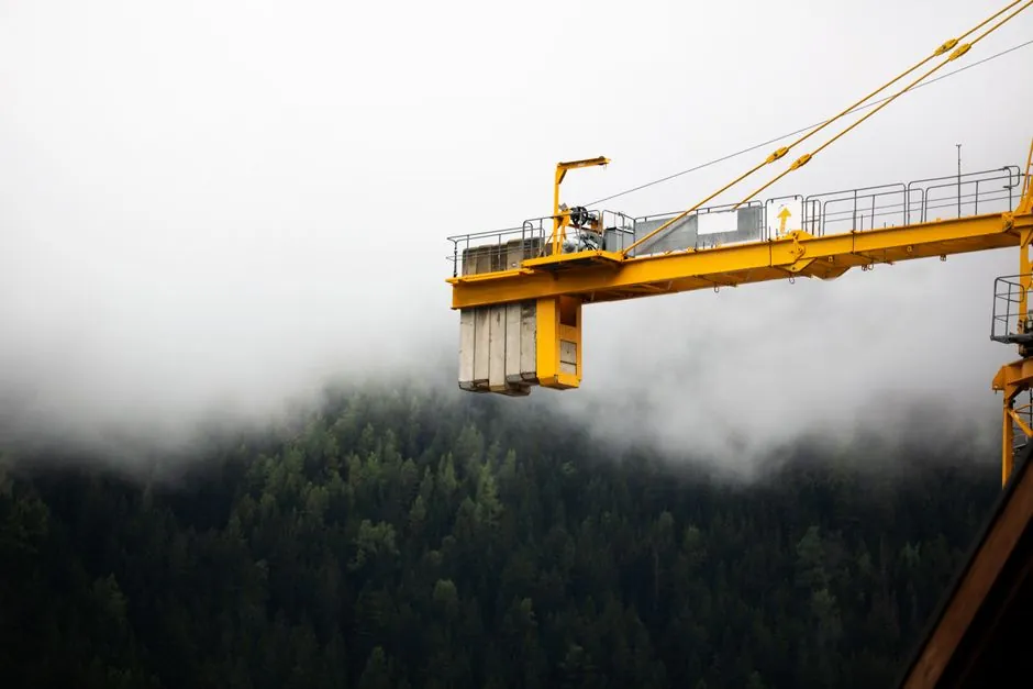
Modern crane instrumentation stacks three transducers: an accelerometer on the trolley or hook block, a strain-gauge load pin on the hoist line, and a rotary encoder on the hoist drum, all feeding a Safe Load Indicator (SLI) that compares live signals against the manufacturer's load chart [S1][S4].
On a typical bridge or offshore crane, the accelerometer measures trolley horizontal acceleration so the anti-sway algorithm can derive pendulum period from paid-out rope length, while the load pin and encoder close the loop on weight, hook position, and hoist upper limit to prevent two-block events [S2][S4].
Why a Crane Accelerometer Is Not a Level Sensor
An accelerometer in crane duty measures linear acceleration, not tilt angle, and that distinction decides where it mounts and what its output means for the controller [S1]. DIS Sensors product line, distributed by Crane Sentry integrator channels, explicitly lists dedicated accelerometer, inclinometer, and tilt switch families, with the accelerometer typically bolted to the trolley or cross-travel gear to read traverse acceleration along the bridge axis [S1]. The inclinometer, by contrast, is used on the boom of a mobile or offshore crane to feed radius and load-moment calculations, and the tilt switch is a binary trip for out-of-level parked conditions [S1][S4]. Picking the wrong one gives the SLI a clean signal that is physically the wrong physical quantity, so a misapplied inclinometer cannot substitute for a sway-control accelerometer on a high-speed trolley [S3].
Load Pin, Wire-Rope Encoder, and Accelerometer: Three Sensors, One Decision
Strain-gauge load cells, load pins, and wire-rope mounted encoders each cover a different failure mode, and pairing them with an accelerometer is what closes the anti-sway loop on a working bridge crane [S2]. Pat Kruger's 2026 teardown of bridge crane load monitoring names strain-gauge load cells and load pins as the two weight-measuring workhorses, with stainless-steel housings specified for moisture, dust, and thermal cycling on the shop floor [S2]. Mipeg X uses winch-mounted absolute encoders to compute hook position from rope paid out, then drives anti-two-block warning, creep speed, and kick-out relay logic as the hook approaches the upper limit [S4]. The accelerometer does not measure weight at all; it reads trolley acceleration, which the controller integrates once to get velocity and feeds into the pendulum-period model so the load can be carried under the hook instead of swinging behind it [S3][S1].
Anti-Sway Physics: Pendulum Period From Rope Length Alone

Anti-sway control rests on a 1602-era observation in Pisa cathedral: the period of a pendulum depends only on rope length and gravity, not on the mass hanging from it, so an accelerometer plus an encoder is enough to predict swing without knowing the load [S3]. For a single ideal pendulum the period is T = 2π√(L/g), which is why the controller only needs L from the hoist encoder to schedule the trolley drive profile; the suspended mass cancels out of the equation [S3]. Real hook-and-rigging setups form a double pendulum, with the hook swinging beneath the boom tip while the load swings beneath the hook, so skilled operators rely on iterative 'catch the load' manoeuvres combining forward driving, drifting, and reverse-plug braking to damp residual sway [S3]. That same logic, expressed as an algorithm, takes the accelerometer's horizontal acceleration signal, computes the inferred swing angle, and modulates trolley speed so the support tracks the load, reducing oscillation at the destination [S3].
Wind Speeds Above 20 mph: Where Accelerometer-Only Anti-Sway Stops Working
Wind gusts above roughly 20 mph, even at moderate elevations, can push a swinging load beyond the predictive range of a pure trolley-acceleration model, so anemometer data has to enter the control loop alongside the accelerometer [S5]. A crane anemometer measures air speed at boom-tip height, where surface winds can be a step higher than what is felt at deck level, and feeds both the load chart derate and the anti-sway gain schedule [S5]. Operators running a 50-ton lift in a 25 mph crosswind cannot rely on the pendulum model alone; the wind applies a continuous lateral force that the accelerometer sees as drift, not as the clean sinusoid the algorithm expects [S3][S5]. NIOSH field studies cited in current NCCCO prep material note that wind gusts are frequently higher than anticipated, which is why modern weather stations bundle anemometer, direction, precipitation, visibility, and load-chart inputs into one operator display [S5].
Selection Criteria: Trolley Accelerometer vs Boom Inclinometer vs Tilt Switch
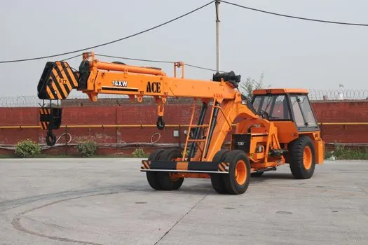
Three decision criteria pick the right transducer for a given crane duty: the physical quantity you actually need, the mount location, and the control-loop bandwidth the SLI expects. First, an accelerometer belongs on the trolley or cross-travel carriage where horizontal traverse acceleration is the variable that anti-sway has to track, while a single- or dual-axis inclinometer belongs on the boom of a mobile or pedestal crane where boom angle feeds the load-moment calculation against the OEM chart [S1][S4]. Second, a tilt switch is a latching safety device, not a control input; it is wired to a hard interlock so a parked crane cannot be left in a known-unlevel state, and it should never be used as a feed to the anti-sway algorithm [S1]. Third, the bandwidth of the accelerometer must cover the pendulum frequency of the longest rope that will be paid out at full hoist height, otherwise the controller sees a smoothed sine wave and applies gain to a signal that has already been low-pass filtered by the sensor itself [S3].
Integration with the SLI: Mipeg X, Crane Sentry, and the Load-Moment Math
Offshore-rated Safe Load Indicators such as Mipeg X are explicitly modular: the base system monitors load, radius, and tipping moment against the OEM load chart, and add-on sensors extend it to anti-two-block, slew-zone mapping, vessel roll and pitch, and hook-position readout [S4]. Crane Sentry hoist monitoring applies the same idea to industrial bridge cranes, where continuous monitoring of hoist line condition plus side-pull detection is paired with collision-avoidance logic across multiple hoists on the same runway [S1]. For a process engineer, the practical decision is whether the SLI needs to interface with an existing PLC over a 4-20 mA and HART loop for the load pin, a CAN or serial link for the encoder, and a discrete input for the accelerometer-derived sway state, or whether a fully integrated vendor display is acceptable [S2][S4]. Load cell module material trade-offs drive the weighing side, while draw-wire encoder selection drives the hoist-position side, and those choices cascade into how cleanly the accelerometer anti-sway loop closes.
Failure Modes and Limits to Plan Around

Three failure modes show up repeatedly in the field: accelerometer saturation during emergency stop, double-pendulum swing that the single-pendulum model cannot damp, and wind loading that overwhelms the control authority of the trolley drive [S3][S5]. An E-stop on a fully loaded trolley can produce accelerations well above the ±2 g or ±4 g range of a typical industrial MEMS accelerometer, clipping the signal exactly when the controller most needs the deceleration profile to predict swing [S1]. A hook-and-rigging double pendulum swings at two frequencies, and a single accelerometer plus single-encoder setup can only null the rope-mode swing, leaving the load swinging beneath the hook until manual damping runs it out [S3]. Wind above 20 mph introduces a steady-state lateral force that no amount of trolley acceleration can counteract without slewing the boom into the wind, so anemometer input must be allowed to override the anti-sway loop and force a lift abort or derate through the load chart [S5].
Applicable Standards and Sourcing Anchors
U.S. crane wind monitoring references OSHA 29 CFR 1926.550 for general crane operation, with rigging and load-chart rules under 29 CFR 1926, plus ASME B30.5 for mobile and locomotive cranes, and NCCCO operator certification with NFPA 70E-2020 electrical-safety overlay for the wind monitoring system itself [S5]. Offshore installations layer class rules and flag-state requirements on top, which is why the Mipeg lineage traces back to North Sea lifting rules from the mid-1970s and is still positioned against current international end-user specs [S4]. For sourcing, the Crane Sentry hoist-monitoring page lists wire-rope and chain hoist variants, side-pull detection, and load monitoring as configurable modules rather than a single SKU, and the same vendor channels carry DIS Sensors accelerometers and inclinometers as separate part families [S1].
Trackable signals for the next quarter: NCCCO wind-monitoring training becoming a formal renewal prerequisite, and continued vendor push to integrate anemometer, accelerometer, encoder, and load pin into one operator display rather than four standalone gauges [S5][S4].
Spec-level background on the components involved: swing check valve, and condition monitoring system.