
Automated Tape Laying (ATL) and Automated Fiber Placement (AFP) split the aerospace composite layup workflow along a single axis: part geometry. ATL applies prepreg tape bands typically 75-300 mm wide from a gantry-mounted head, exceeding 50 m/min on flat or gently curved tooling such as wing skins and fuselage barrel sections [S4]. AFP, by contrast, deposits multiple narrow tows of 3.2 mm or 6.35 mm slit unidirectional tape, each individually start/stop/cut/restart capable, which is why AFP is the only viable automated option for highly contoured structures including engine nacelle components, inlet ducts, and fuselage frames [S4].
The aerospace AFP/ATL composites market reached USD 5.6 B in 2025 and is on track for USD 6.1 B in 2026, a 9.3% year-over-year rise, with an 8.6% CAGR projected to USD 11.9 B by 2034 per Stratview tracking dated 2026-09-28 [S5]. That trajectory tracks wider adoption on the Boeing 787 and Airbus A350 airframes, both of which pushed past 50% composite structural weight, and it lines up with narrowbody build-rate targets of 60+ aircraft per month where manual layup is no longer practical [S4][S5].
Tape Width, Tow Count, and Deposition Rate: Where Each Process Wins
ATL productivity comes from tape width: a single 300 mm course covers the same area as roughly 47-94 AFP tows at the common 3.2-6.35 mm widths, which is why ATL clears flat or single-curvature skins faster and cheaper [S4][S7]. AFP productivity is bounded by tow count: heads running 16 or 32 tows deliver 10-25 kg/h of material deposition depending on part complexity, and independent tow cut/restart lets AFP follow a complex ply boundary without leaving scrap ladders behind [S4]. Both processes share the same downstream constraint: the path-planning software must enforce steering limits, gap/overlap tolerances, and ramp-up/ramp-down zones at ply drop-offs, because aggressive steering buckles fibers and excessive gaps create resin-rich weaknesses [S4].
Geometry is the hard divider. ATL heads cannot conform wide tape to compound curves without wrinkling or bridging, so ATL stays on wing skins, fuselage barrels, and large panels. AFP heads steer narrow tows and follow contours, which makes AFP standard for nacelles, inlet ducts, fuselage frames, and any double-curvature component [S4][S5][S6]. Toray CMA describes the practical split as "AFP deposits multiple, thin tows of slit unidirectional tape, ATL is best for quick layup of simple geometries," and the Jota Academy 2026-02-24 comparison frames the same divide around tow vs tape width, speed, scrap, and geometry limits [S6][S7].
Selection Criteria: Speed vs Conformity vs Scrap
For a process engineer choosing between ATL and AFP on a new aerospace part, three criteria carry the decision. Throughput: ATL hits above 50 m/min on flat sections while AFP holds 10-25 kg/h with a 16 or 32 tow head, so on area-only parts ATL wins on cycle time [S4]. Conformity: AFP handles tight radii and compound curves that ATL wide tape cannot, so on contoured parts AFP is the only choice [S4][S6]. Material yield: AFP's per-tow cut/restart cuts scrap on complex ply drops, while ATL on a flat skin leaves near-zero trim waste but generates offcut at every ply boundary [S4][S7].
A clean rule of thumb from the supplier literature: pick ATL for large, gently curved surfaces where speed dominates, and pick AFP for complex, curved components where conformity dominates. Stratview's 2026-09-28 segmentation supports the same split, noting airframe as the dominant application segment and engine components as the fastest-growing slice as nacelle and inlet-duct programs scale [S4][S5]. Prepreg tack, compaction force, and head heating are held constant across both processes, which means downstream cell layout, kitting, debulk, and inspection steps look almost identical regardless of which head a plant standardizes on [S4].
Process Cell Integration: Kitting, Debulk, and AFP/ATL Adjacent Steps
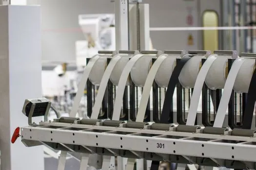
Automated kitting cuts prepreg plies with ultrasonic knives or CNC cutters, labels them with ply identifiers, and sequences them for the layup head, which removes the manual nesting errors that drove aerospace OEMs to automate in the first place [S4]. Between layup sequences most structures still need debulk cycles, vacuum consolidation that pulls trapped air from between plies, and modern cells automate the bag placement, vacuum pull, and pressure-decay check that used to interrupt the layup flow with a labor-intensive step [S4]. The same logic flows downstream: automated drilling and fastening cells handle the next operation once the laminate is cured, with spec, force, and cycle benchmarks that line up with AFP/ATL throughput assumptions in a single airframe cell [S4].
For inspection, ATL and AFP parts share the same non-destructive testing (NDT) burden because both processes still require verification of internal quality after cure. Inline thermography, ultrasonic C-scan, and laser-line scanning get specified at the cell level rather than the head level, which keeps the head-buy decision separate from the inspection-buy decision [S4]. The Cevotec September 2026 announcement, naming KCompositeLab as South Korea sales partner for the Samba robotic lamination equipment, points to a parallel trend: smaller robotic cells aimed at aerostructures and composite pressure vessels, complementing the gantry-scale AFP/ATL cells on the major airframe lines [S2].
AFP/ATL Market Sizing 2026-2034 and Segment Growth
Stratview Research's 2026-09-28 report on the Aircraft AFP/ATL Composites Market states that annual demand was USD 5.6 billion in 2025 and is expected to reach USD 6.1 billion in 2026 (up 9.3% YoY) and USD 11.9 billion in 2034, with a cumulative 2026-2034 sales opportunity of USD 79.0 billion [S5]. By application, airframe stays the dominant segment while engine components grow fastest, which lines up with the geometry split above: ATL-heavy wing and fuselage programs drive the bulk, AFP-heavy nacelle and inlet work drives the growth [S5]. By aircraft type, wide-body platforms remain the growth engines of the market; by fiber, carbon fiber composite stays the most dominant and fastest-growing fiber type through 2034 [S5].
Geographically, North America is projected to remain the largest and fastest-growing region across the 2026-2034 forecast window, supported by the Boeing 787 and the next narrowbody ramp plus Tier-1 aerostructure suppliers concentrated in the U.S. [S5]. The 2025 top-10 country share was USD 4.5 B, north of 80% of the global pool, and the 2025 top-10 supplier share was USD 2.8-3.9 B, or 50-70% of the market, which is a relatively concentrated supplier base for what looks like a fragmented process landscape [S5].
Limitations, Failure Modes, and Open Trade-Offs
ATL's main failure mode is geometric: wide tape bridges on compound curves, producing wrinkles and out-of-tolerance laminates that scrap the part or require manual rework [S4]. AFP's main failure modes are process-side: aggressive tow steering buckles fibers, gap/overlap drift creates resin-rich zones, and foreign-object debris or backing-paper issues at the cut/restart point can drop a tow mid-course [S4]. Both processes depend on consistent prepreg tack, head temperature, and compaction pressure, so material storage, out-time tracking, and cell environmental control are upstream gating items that the head choice cannot fix [S4].
Open trade-offs in the supplier landscape matter. A 2026-06-02 Fortune Business Insights ranking of automated fiber placement companies notes AFP is often preferred over ATL on complex geometries, with proprietary methods cited as the productivity and accuracy lever (e.g. MTorres' TorresFIBERLAYUP platform) [S8]. The 2024 review by Carosella and colleagues frames AFP and ATL as complementary rather than competing for the same part, which matches the geometry-based selection rule above [S3]. Aerospace build-rate pressure to 60+ narrowbody aircraft per month is the forcing function that keeps both process families funded, since neither ATL nor AFP alone can cover a full airframe at that rate without a mixed cell [S4].
Sourcing, Standards, and Decision Matrix
Process selection on a new airframe program flows from three inputs: ply geometry (compound curvature flags AFP, single curvature flags ATL), annual part count (high-rate favors ATL throughput, low-rate complex favors AFP conformity), and material yield target (AFP cut/restart trims scrap on complex drops, ATL minimizes trim on simple skins) [S4][S7]. For readers building a broader composites manufacturing reference, the FRP composite encyclopedia entry covers the material side of the same workflow, while the industrial valve page is a useful reminder that high-pressure cure fixtures downstream of layup still rely on conventional process hardware. Aerospace suppliers evaluating cell-level sensing and control upgrades can cross-reference the pressure transmitter and flow meter encyclopedia pages when specifying autoclave instrumentation.
Trackable signals to watch next: the 2026-2034 Stratview forecast revision in 12 months to confirm the 8.6% CAGR holds, the next Fortune Business Insights supplier ranking to see whether MTorres and Tier-1 incumbents keep their share, and any 2026-2027 OEM disclosure on narrowbody composite content that would re-rate ATL throughput assumptions [S5][S8]. For adjacent spec decisions, the automated drilling and fastening cells article covers the next cell in the same airframe flow, and the industrial adhesive dispensing method piece covers a separate but related process decision that often sits one cell over from the layup head.