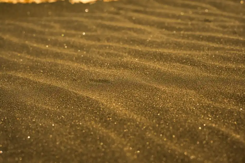
Shell molding sand is specified at AFS 100 or higher, versus AFS 60–80 for green sand, because finer grains reproduce pattern detail and surface finish at the cost of gas permeability [S3].
The American Foundry Society's AFS grain fineness number is the controlling metric: higher numbers mean smaller average grains, and shell process foundries target 100+ for standard work and up to 150 for premium surface reproduction [S3].
AFS 50–70 Base Silica with 1–2 wt % Phenolic Resin Coating
Resin-coated shell sand starts from high-purity silica at AFS 50–70, uniformly coated with 1–2 wt % thermosetting phenolic or epoxy resin; this base grain range balances flowability into the investment box with enough surface area for resin bridging [S1]. The hot-coating process dissolves novolak flake resin into a solvent, coats hot sand in a muller, and dries the coated grains before they are dumped into a heated pattern or shell core shooter magazine [S4].
Once invested against a pattern at 200–260 °C, the resin softens, flows, and partially cures to bond adjacent grains, then the assembly is oven-cured to advance the phenolic to a rigid shell that pops off the pattern as a half-mold (a "biscuit") [S4]. Calcium stearate at 2.5–5 % of resin solids weight is the standard flowability and release additive, and at that loading it nearly doubles tensile strength and significantly increases shell density versus uncoated controls [S4].
Why AFS 100+ Beats AFS 60–80 for Detail Reproduction
Finer sand packs more densely against the pattern surface, conforming to micro-features down to roughly 0.1–0.3 mm wall transitions and reducing peak surface roughness on the cast face; the trade-off is reduced permeability, which the shell process tolerates because shells are dried and hot-cured, with no free water to flash into steam during pouring [S3]. Green sand at AFS 60–80 relies on bentonite-bound moisture that must vent as water vapor, so it cannot tolerate the same packing density without gas defects [S3].
Draft angles tighten with finer stock: green sand patterns typically need 2–3 ° of draft, while shell at AFS 100+ runs 1 °, and short vertical walls can be drafted at zero because the rigid shell releases cleanly off a heated metal pattern [S3]. For even tighter replication, foundries substitute zircon sand at AFS fineness up to 150, which also drops the thermal expansion coefficient and allows tighter as-cast dimensional control [S3]. The downstream cost is abrasive wear on the shell molding machine pattern surfaces and tooling, which zircon accelerates relative to silica.
Resin Chemistry, Hot-Coat Process, and Cure Cycle
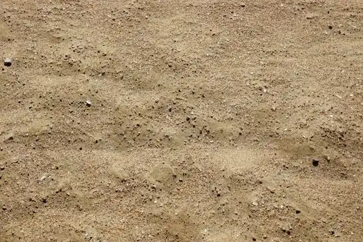
Phenolic novolak is the dominant binder, with over 80 % of North American shell resin supplied in solvent-free flake form, hexamethylenetetramine (hexa) acting as the hardener that cross-links the novolak under heat [S4]. Early Croning process work used dry-blended powdered resin and hexa, which could only be gravity-fed or hand-rammed; the mid-1950s shift to liquid resin dissolved in alcohol unlocked blowable, dust-free coated sand for core production, and warm-air injection into the coater accelerated solvent removal [S4].
Modern hot-coat lines run either waterborne or solvent-borne systems; waterborne hot coating emerged when manufacturers found they could dissolve resin in water-diluted solvent and apply it to hot sand without flashing the solvent prematurely, eliminating alcohol emissions from the coater [S4]. Bench life of the coated sand is governed by resin advancement during storage, and foundries running fine-detail shell mold cores typically hold stock inventory below two weeks to preserve flowability and tensile development. For foundries running matched resin-sand-line systems, the coated sand must reach a tensile strength of roughly 350–500 psi on the hot-strength test before pattern dump to survive handling.
Selection Criteria: AFS Fineness vs Application
Foundries pick AFS fineness by mapping it against four decision criteria: surface roughness target, dimensional tolerance, draft allowance, and tooling wear budget. [S1]
AFS 50–70 coated sand is the general-purpose shell stock, good for draft angles of 1–1.5 ° and as-cast tolerances of ±0.5 %; AFS 100–120 is the fine-detail tier, supporting 0.5–1 ° draft and ±0.3 % tolerance, and is the workhorse for hydraulic valve bodies and small armatures [S3]. AFS 130–150 in zircon is the premium tier for medical, aerospace, and thin-wall aluminum components where surface finish and tight tolerance dominate the cost equation, at the price of faster pattern erosion [S3]. Reference synthetic-resin selection should also account for gas evolution, which phenolic holds at ≤0.2 L/kg sand versus 0.3–0.5 L/kg for furan systems in chemically bonded comparisons [S1].
Limitations: Permeability, Gas, and Tooling Wear
Three failure modes follow from running AFS 100+ shell sand: reduced permeability, resin gas evolution, and accelerated pattern abrasion. Permeability numbers for fine silica shell sand typically land at 80–150 AFS permeability units, well below the 200–400 PN common in green sand, so any residual moisture in the shell will flash and blow the cavity [S1].
Phenolic gas evolution at pour temperature can reach 0.2 L/kg sand, which is why shell cores are vented through the mold or use permeable back-fill, and why AFS 1114-00-S acid demand value testing is part of incoming sand QC at most North American foundries [S1][S6]. Pattern wear on shell-core-machine tooling is the silent cost: every thousand cycles at AFS 130+ removes measurable micron-level stock from the pattern face, and high-volume foundries schedule pattern re-polishing on cycle counts rather than calendar time. For foundries running aluminum pours, a related constraint surfaces in mold material selection logic, where finer sand is doubly justified by lower pouring temperature and tighter alloy flow requirements.
Testing, Standards, and Sourcing
Incoming coated sand QC at most foundries runs AFS sieve analysis for grain fineness, tensile and hot-strength tests for resin development, and the AFS 1114-00-S acid demand value test for catalytic residue that can poison the phenolic cure [S6]. Suppliers including HA International and Covia publish AFS fineness ranges and tailor base grain to the foundry's peek process window, with HA emphasizing customizable resin formulations for shell and core work [S2][S7].
Trackable signals worth watching: AFS fineness distributions on supplier datasheets (Covia's INCAST line publishes tailored AFS bands), calcium stearate loading shifts above 5 % of resin solids, and any move by major automotive shell-mold foundries toward AFS 130+ silica to consolidate post-machining operations. Standardization note: the AFS fineness number is defined by AFS Mold & Core Test Handbook procedures, not by an ASTM or ISO sieve-cut designation, so cross-referencing supplier AFS numbers to mesh-size requires the AFS-published conversion table rather than a direct ISO 565 sieve callout [S6].