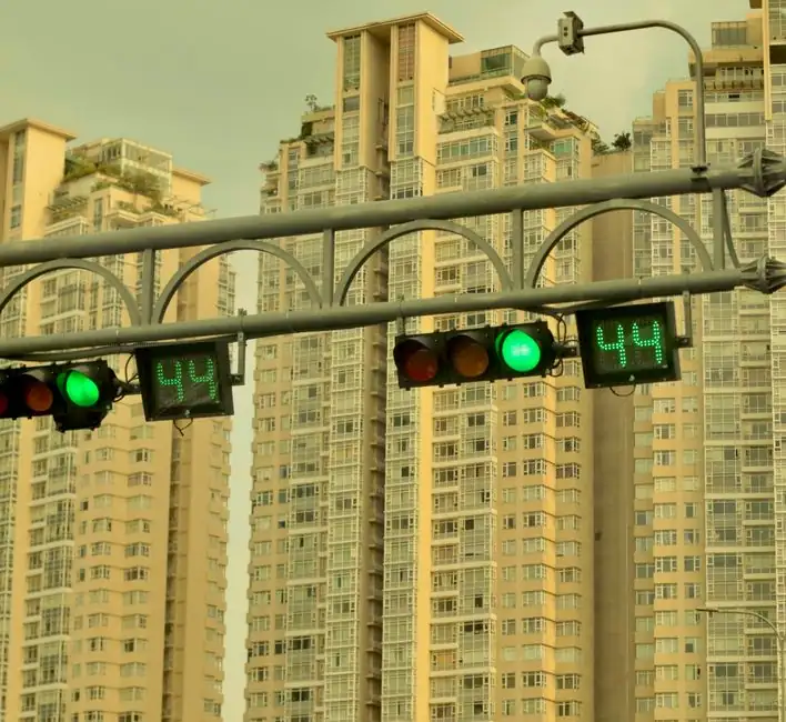
An on-delay timer holds the alarm inactive until the process variable has been in the trip state for a defined window (commonly 1-5 s on fast loops, 10-30 s on slower process variables) before the annunciator is raised [S2][S3].
The countermeasure sits inside a wider alarm-management lifecycle defined under ISA-18.2 / IEC 62682 and benchmarked against EEMUA 191, where nuisance alarms are treated as a design defect, not an operator nuisance [S4]. Setra lists eight configurable features, including a time-delay buffer and a flutter buffer, as the minimum toolkit for a pressure sensor-driven alarm channel [S5].
On-Delay, Off-Delay and De-Glitch: Picking the Right Timer
An on-delay (process-condition must persist) suppresses fleeting spikes from motor starts, relay switching and valve closures, with 1-2 s quoted as a typical de-glitch value in remote-site monitoring [S3] and 2-3 s quoted as a PLC filter for pressure/level channels [S2]. An off-delay (alarm stays latched after the condition clears) prevents chattering when the process oscillates around the trip point and is the standard fix for a noisy signal that re-enters the trip band repeatedly [S1]. The rule of thumb from hexagon operations: on-delays of 30 s or less are acceptable for lower-priority alarms; anything longer than 30-60 s demands a written justification because it begins to mask real upsets [S6].
Davicom's remote-site data shows a 2-second de-glitch window is enough to absorb motor-start transients while still capturing a real 20-30 s audio-silence event, illustrating the tradeoff: shorter windows protect more real alarms, longer windows kill more false ones [S3]. The window should be field-tunable, with practical adjustment ranges cited from 1 second up to several minutes depending on the monitored variable [S3].
Deadband and Hysteresis: Stopping the Switch From Cycling
Deadband is the change required in the process variable to clear an alarm once it has activated, effectively a hysteresis band around the trip point [S1]. On a binary switch, a wider mechanical differential prevents contact chatter and PLC logic confusion; on a continuous transmitter, deadband is normally entered as a percentage of the measurement range [S1][S2]. The risk is real: on a 100,000-unit flow span with a 2% deadband, the alarm will not clear until the reading is 2,000 units below the trip, a latching condition that can hide a slowly drifting process [S1].
Whitman's design guidance for pressure and level switches recommends piston-actuated elements over diaphragm elements in high-vibration service because the higher moving mass and internal friction resist shock-induced cycling, a physical-layer fix that complements the deadband setting [S2]. For electrical loads, adjustable trip-delay settings on the protective device accommodate motor inrush without an overcurrent trip, a parallel technique applied at the breaker rather than the sensor [S2].
Signal Averaging and Filtering: Smoothing Before the Trip Test

Filtering and moving-average blocks smooth a noisy signal so the filtered value does not exceed the high setpoint even when the raw value does, eliminating one class of false positive without changing the trip level [S1]. On an Allen-Bradley PLC-5 platform, the documented fix for a rate-of-change temperature alarm that nuisance-trips from electrical noise is a moving-average or debounce block applied in ladder logic, implemented before the rate calculation [S9]. Filter time constants must be selected against the loop dynamics: too long a filter on a slow process delays alarm activation, and around the setpoint it can hide a real excursion entirely [S1].
Setra's 8-feature list for nuisance-alarm reduction adds a flutter buffer (suppress repeated crossings within a defined window) and state-based arming (only allow certain alarms during specific operating states) as the filter's companions [S5]. For vibration-coupled noise, the mechanical-layer fix is remote mounting on a stable bracket with a flexible capillary, physically decoupling the gas alarm controller or fire alarm control panel input from the pump or compressor frame [S2].
Comparison: Which Technique Fixes Which Failure Mode
Four countermeasures against four common failure modes, drawn from the sources: (1) on-delay / de-glitch, 1-5 s, kills fleeting transients from motor starts and valve closures, cannot fix a sustained near-setpoint oscillation [S2][S3]; (2) off-delay, 1-30 s, kills chattering on a noisy near-setpoint signal, will mask a real re-entry if set too long [S1][S6]; (3) deadband / hysteresis, 1-5% of span, kills contact bounce and binary switch cycling, risks latching on wide-range transmitters [S1][S2]; (4) moving-average / low-pass filter, time constant matched to loop, smooths noise before trip logic, slows response on slow loops and can hide setpoint drift [S1][S9]. Whitman's piston-vs-diaphragm and remote-mount mechanical fixes layer underneath all four for vibration environments [S2].
When NOT to Lengthen the Delay
Control Global's core warning: a delay that goes from 5 seconds to 5 minutes is rarely the correct fix, because the technique that did not resolve the false positives at 5 s will not resolve them at 5 min, and the new delay will mask real alarms whose response time is shorter than the timer [S1]. On safety instrumented functions, the delay is constrained by the required safety integrity level (SIL) response time, and a poorly tuned on-delay can push the average probability of failure on demand outside the SIL target. The fix is to stack two complementary techniques (for example, a short 1-2 s de-glitch plus a small 1-2% deadband) rather than extend a single timer [S1][S3]. ISA-18.2 / IEC 62682 require that any change to delay or deadband settings be captured under management of change, with periodic KPI review to confirm the alarm rate has actually dropped rather than the real alarms being silently suppressed [S4].
Selection Criteria: Match the Filter to the Loop, Not the Symptom
For a fast electrical loop (motor current, relay contact) start with a 1-2 s de-glitch and no filter, since the loop itself is already fast and the only goal is to ride through the inrush [S2][S3]. For a slow process variable (level, temperature) the right starting point is a moving-average or exponential filter with a time constant of one-tenth to one-quarter of the loop's natural period, plus a 1-3% deadband [S1][S9]. For a chattering switch on a vibrating skid, the fix is mechanical first (piston element, remote mount, snubber) and deadband second; do not solve a vibration problem with a software delay [S2]. The Whitman checklist also calls out surge suppressors on the electrical side and mechanical snubbers on the pressure side as parallel physical fixes that reduce the load on the software timer [S2].
Embedded Standards and Sourcing
The governing references cited in current alarm-management literature are ISA-18.2 (alarm lifecycle for the process industries), IEC 62682 (its international counterpart), and EEMUA 191 (alarm-rate benchmarks, standing-alarm and chattering-alarm guidance) [S4]. Hexagon's operations guidance supplies the 30 s / 60 s engineering rule for on-delay duration as a function of alarm priority [S6]. A 2018 generalized performance-index study of delay-timers (Lin, tandfonline, 2018) confirms the technique is widely deployed in practice as a nuisance-alarm countermeasure [S7]. Whitman Controls and Setra supply vendor-level implementation patterns; for a checking and testing apparatus used to verify the resulting trip point, deadband must be re-measured after every filter change.
Trackable signal for the next planning cycle: re-baseline the alarm rate KPI under EEMUA 191 (alarms per operator per hour, standing-alarm count, chattering-alarm count) before and after any delay or deadband change, and archive the management-of-change record against the affected loop's P&ID and cause-and-effect matrix [S4]. Two linked engineering references worth pulling into the same review are Digital FMEA Linked to Control Plans: 2026 Software Stack and Audit Reality and Addressable vs Conventional Smoke Detector Wiring: Loop vs Radial Decision Guide, both of which touch the alarm-design boundary this article sets up.