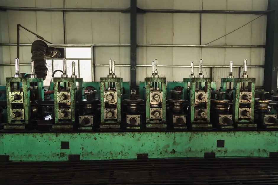
On a horizontal cold-chamber aluminum die casting machine, holding the shot sleeve fill ratio between 50% and 75%, with 60% as the working target, is the single most leveraged setting a process engineer can dial to cut gas and shrinkage porosity [S5][S2].
The fill ratio is the molten metal volume loaded into the shot sleeve divided by the sleeve's geometric capacity, expressed as a percentage; running it below ~50% leaves a large air cushion that the slow-shot phase compresses and entrains, while pushing it past ~75% starves the plunger of travel and forces a faster, more turbulent slow shot [S5][S8]. For common alloys like 380 and 384 aluminum the intensifier then has to make up the difference with 27-40 MPa of packing pressure applied during the semi-solid freezing window (80-120 °F for 380/384 respectively) [S2][S3].
Why the 50-75% window matters in the slow-shot phase
A Korti and Abboudi (2017) study in the International Journal of Metalcasting showed that the air entrapment originating in the slow-shot phase of a horizontal cold-chamber HPDC machine is one of the dominant sources of casting porosity, and that the fill ratio of the sleeve at the moment the plunger starts to advance controls the shape of the free surface and how that surface solidifies before injection [S4]. In practice, a 60% fill produces a short, stable metal column ahead of the plunger tip, which keeps the slow-shot velocity near the ~0.5 m/s entrainment threshold stated in the NADCA-style PQ² guidance instead of spiking above it [S2][S5].
The same study framed sleeve filling as a gravity-pour-into-tube problem: pour too little, and the impact wave at the sleeve wall traps an air pocket that the plunger later compresses; pour too much, and the metal reaches the pouring hole before the plunger seals it, creating a back-flow path that injects oxide into the melt [S4][S8]. Both failure modes are routinely visible as subsurface gas porosity on X-ray and as blistering after impregnation or machining, which is the symptom the original 2016 CR4 thread was chasing when an aluminum oil-channel component kept rejecting leak tests [S1].
How fill ratio ties to plunger diameter, stroke, and machine tonnage
Plunger sizing is a direct consequence of the chosen fill ratio: D = sqrt(4 × V_shot / (π × Fill% × L_stroke)), where V_shot is the casting plus runner plus overflow volume, Fill% is the decimal fill (0.50-0.70 typical), and L_stroke is the available plunger travel [S2]. Common plunger diameters for cold-chamber aluminum cells sit at 50-60 mm on 250-ton machines, 70-80 mm on 500-ton machines, 90-110 mm on 800-ton machines, and 130-160 mm on 1600-ton machines, all chosen so the geometric fill lands inside the 50-70% band [S2].
Two practical constraints bound that band. First, sleeve thermal expansion is on the order of 0.01 mm/mm at a 200 °C sleeve temperature, which slightly changes the real fill ratio versus the cold geometric value and has to be checked against the machine's actual stroke length rather than the catalog number [S2]. Second, plunger-tip radial clearance is typically 0.05-0.15 mm; once the tip wears into the upper half of that band, blow-by lets melt bypass the plunger and the effective in-sleeve volume falls, pushing the process toward under-fill even when the calculated ratio looked healthy [S2].
Comparing fill-ratio options against the four decision criteria
The decision is not a single number but a four-axis trade, so lining the three operating bands against cost, porosity risk, machine fit, and throughput makes the choice auditable. A side-by-side of the three commonly cited bands, drawn from the same practitioner sources, looks like this: [S5]
<b>Fill < 50% (e.g. 30-45%):</b> Lowest melt cost per shot because less metal is loaded, but the air column above the metal is large; slow-shot velocity drifts above 0.5 m/s to keep cycle time, and gas porosity plus oxide entrainment both rise sharply. Not recommended for any pressure-tight aluminum part [S5][S8].
<b>Fill 50-70% (NADCA starting band, 60% optimum):</b> Best balance for cold-chamber aluminum; slow-shot stays in the laminar regime, intensification pressure of 27-40 MPa can pack the semi-solid freezing range, and plunger sizing matches standard 250-1600 ton machine bores. This is the default the calculators and the ZHY practitioner guide converge on [S2][S5].
<b>Fill 70-75% (upper practitioner limit):</b> Acceptable for thin-wall, high-speed castings where extra metal cushions the abrupt slow-to-fast transition, but cuts usable plunger stroke, raises sleeve thermal load, and leaves little margin for melt-temperature dips. ZHY's guide quotes 60-75% as the practical ceiling [S5].
<b>Fill > 75%:</b> Outside published guidance. The plunger runs out of travel, the slow-shot phase compresses, and the metal frequently overruns the pour hole, producing the same air-entrapment failure mode the under-fill case causes but with a higher loaded-metal cost penalty [S5][S8].
Coupling fill ratio with slow-shot, intensification, and alloy behavior
Fill ratio is necessary but not sufficient. The slow-shot velocity for an aluminum cold-chamber cell should sit at roughly 0.5 m/s, a rule of thumb often expressed as V_slow ≈ D/100 m/s where D is the plunger diameter in mm, with a 0.2 m/s floor for small plungers [S2]. Below this velocity the metal starts to freeze on the sleeve wall; above it the surface breaks up and entrains air regardless of how well the fill ratio was set [S2][S5].
Once the cavity is filled, the intensification stage applies 27-40 MPa of static pressure during solidification to feed shrinkage voids as they form inside the 80-120 °F freezing range of 380 and 384 aluminum alloys (15 °F for 413, 230 °F for AZ91D magnesium, 10 °F for Zamak 3 zinc) [S2][S3]. Timing is everything here: applying pressure while the metal is still liquid only adds flashing, while applying it after the casting has fully solidifies is wasted tonnage; the useful window is the semi-solid mushy zone [S3]. For thin-wall motor housing geometry this is precisely the case where aluminum die casting machine selection for motor housings has to be matched to the intensification ramp, not just the clamping force.
Limits, failure modes, and where 60% is the wrong answer

Three situations break the 60% rule. Vacuum-assisted HPDC cells, which evacuate the sleeve before the plunge, can tolerate lower fill ratios because the air cushion has already been removed; conversely, the ZHY practitioner guide and the YZ Casting engineering reference both require ≥ 50% as a hard floor for non-vacuum production cells [S5][S8]. Hot-chamber magnesium die casting runs at a different sleeve geometry entirely, so the 50-70% number from the cold-chamber aluminum calculators does not transfer directly; engineers moving from aluminum die casting machine selection for thin-wall electronics enclosures to magnesium work have to re-derive the band on a magnesium die casting machine cell.
The other failure mode is the shot sleeve itself: worn bores, excessive lubrication pooling, and cold-start pours all push the real fill ratio off the calculated value. A sleeve that has lost 0.05-0.15 mm of radial clearance at the plunger tip will under-fill at the same nominal setting, and the only reliable field check is a PQ² trace of position versus hydraulic pressure during the slow-shot phase, paired with a periodic velocity-window audit [S2][S6]. Shibaura Machine's TOSCAST shot-feedback controller, for example, is built around enforcing that velocity window automatically rather than trusting a fixed fill number [S7].
Sourcing, standards, and what to track on the next data point
The 50-75% range and the 60% optimum cited here are practitioner numbers consolidated by NADCA-style PQ² methodology and republished by calculation tools, OEM blogs, and ISO/ASME-cited engineering references; the slow-shot velocity, intensification pressure (27-40 MPa), and alloy freezing-range figures all trace to the same body of work [S2][S3][S5]. The Korti and Abboudi paper in the International Journal of Metalcasting (DOI 10.1007/s40962-016-0051-5) is the peer-reviewed anchor for the free-surface and solidification argument, and the 2017 and 2024 follow-ups confirm that ladle pouring dynamics continue to dominate the air-entrainment budget regardless of fill ratio [S4].
Trackable signals for the next process review: (1) the slow-shot velocity profile captured by the shot controller on at least 20 consecutive cycles, compared against the 0.5 m/s target; (2) X-ray or pressure-leak test yield stratified by fill ratio band, looking for the porosity knee at 50% and 75%; (3) plunger-tip radial clearance measured at every preventive maintenance interval, replaced as it approaches the 0.15 mm upper bound. The die casting machine and shot sleeve encyclopedia entries carry the geometric definitions; the underlying physics is the same whether the cell is a standard cold-chamber unit, a vacuum die casting machine, or a gravity die casting machine used for benchmark pours.