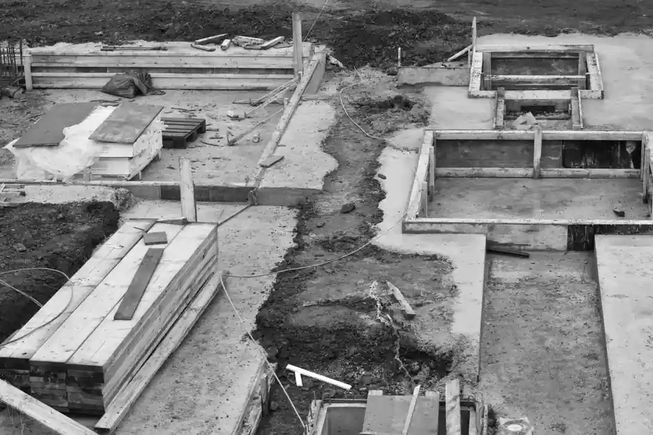
Anchor rod projection above concrete (pc) is defined as the distance from the top of concrete to the top of the rod, with the concrete datum taken from the bottom of the grout pad, not the structural slab [S2].
For the leveling-nut method, the rod must clear two heavy nuts, two thick washers, the base-plate thickness, and a 25 to 50 mm grout cavity, so a practical pc for 19 to 38 mm (3/4 to 1-1/2 in.) rods on typical column bases lands in the 75 to 150 mm range [S1][S2].
Why the Projection Number Drives Erection Geometry
For small to medium base plates up to roughly 560 mm (22 in.) across, leveling plates (often 6 mm, or 1/4 in. thick, sheared to plate size) are usually more efficient, but for larger plates the leveling-nut method dominates because it lets the erector set elevation and plumb independently of the foundation crew [S1].
The projection must simultaneously satisfy three geometric constraints: (1) enough thread above the top nut to tension it, (2) enough rod between the top and bottom nuts to seat the base plate plus grout, and (3) enough rod below the bottom nut to develop the embedment hook or stud head [S1][S2]. Ricker’s 1989 AISC Engineering Journal guidance requires a nut and heavy erection washer both above and below the base plate, which is the geometric driver of the projection dimension [S1].
Setting the Three Methods Side by Side
Three landing-site options compete on the same column footprint, and projection above concrete behaves differently in each [S1]:
Method 1, leveling plates: projection pc is short (often 25 to 50 mm) because the leveling plate is grouted first and the base plate lands on it; the rod only needs to clear the base plate plus a top nut and washer [S1]. Method 2, leveling nuts: pc must clear base plate, grout cavity (~25 to 50 mm), top nut (~rod diameter), top washer, plus thread engagement, summing to roughly 75 to 150 mm for 19 to 38 mm rods [S1][S2]. Method 3, preset base plates: pc is essentially zero because the plate is embedded into the foundation pour, with anchor rods cast in afterward [S1].
A criteria-based comparison: leveling plates offer the best tamper-proof accuracy for plates up to ~560 mm and a solid moment-resistant contact surface, but they cap out in size; leveling nuts scale to any base-plate dimension and any number of anchor rods, at the cost of requiring the larger pc and the risk that the bottom nut is missed during concrete placement; preset base plates give the highest accuracy but require the foundation and the column to be sequenced together [S1].
Where the Grout Pad and the Projection Interact
Grout is modeled as concrete beveled at 45 degrees, and the bottom of grout is treated as the top of concrete datum for projection purposes, which is why SDS/2 and Advance Steel both key pc off the bottom-of-grout plane rather than the structural slab top [S2][S4].
A field failure mode documented on the ASCE Collaborate forum is a gap opening between the grout base and the base plate when leveling plates are used: the leveling plate was cast into the grout pour, and without bottom nuts the column could not re-seat against the grout even under service load, because the leveling nuts, where present, prevent the base plate from moving downward to close the gap [S3]. The corrective action in such cases is to verify that a grout base without a leveling nut path is not relied on for load transfer, and that the projection is long enough to allow both top and bottom nuts to be installed after the base plate is set.
Selection Criteria for Rod Type and Projection
Three rod types map to different projection behaviors in the BIM model: straight rods with threaded ends accept a top nut, a bottom nut, and a bottom washer, so they work with the leveling-nut method; hook rods have a 90 degree bend radius and length set in the model and typically rely on embedment rather than a bottom nut, which restricts usable pc; stud rods carry a forged stud head at the bottom of the shaft, and their overall length equals pc plus embed, making them dimensionally predictable for detailing [S2].
For a given column, the engineer selects steel grade (commonly ASTM A36 or A572 round bar per the project’s round-and-square-bar grade list), rod diameter, and rod type, then back-solves projection from the base-plate thickness plus grout clearance plus nut stack-up [S2]. Common grades F1554 Grade 36, Grade 55, and Grade 105 cover most leveling-nut applications, with the heavier grades requiring more careful attention to thread engagement length above the top nut because higher-strength rods have lower ductility and are less forgiving of under-engagement. Sequence the anchor rod as a separate piece-mark in the model (e.g., prefix AR_) so its length is independent of the column member, and so the projection is regenerable when the base plate thickness changes [S2].
Use Cases and Constraints on the Jobsite
For light-pole and sign-cantilever bases, projection is often minimal and the base plate sits directly on the concrete pier with no grout, transferring load through the anchor rods alone rather than through bearing, which is acceptable because the axial demands are small and the moment arm is short [S3].
For primary building columns, the leveling-nut method is the workhorse: the erector stands the column, sets the bottom nuts to elevation, hangs the base plate on the top nuts, plumbs the column, then torques the top nuts; this sequencing only works if pc accommodates the full hardware stack plus grout-clearance plus thread stick-out, and if the embed depth below the bottom nut is enough to develop the rod in tension [S1]. For heavy industrial columns with base plates above ~1 m on a side, the leveling-nut method is essentially the only practical option because preset base plates would have to be cast to extremely tight tolerance and leveling plates become unwieldy to ship and set [S1].
Modeling, Detailing, and Trackable Signals
In SDS/2 and Advance Steel, the anchor-rod macro models grout as a 45-degree-beveled concrete pocket, with the top of the rod at the modeled pc and the bottom of the rod at the embedment tip, and the macro is expected to feed the anchor-bolt elevation directly into the drawing’s anchor-bolt detail so the field crew sees the same pc the detailer used [S2][S4].
To verify a leveling-nut design before release, check that pc is at least (base-plate thickness) + (grout clearance, typically 25 to 50 mm) + (top nut thickness) + (top washer thickness) + (minimum thread stick-out above top nut, typically 1 to 2 rod diameters), and that the embed length below the bottom nut satisfies the development length required by the chosen concrete and steel strengths. For related detailing practice on cast-in-place hardware in process equipment, see the encyclopedia entry on chemical anchor for adhesive alternatives where the leveling-nut method is impractical, and the expansion anchor reference for post-installed mechanical anchoring where existing concrete limits embed depth. Track the next two signals: the project’s AISC Steel Construction Manual update cycle, which historically has revised anchor-rod detailing guidance, and the ACI 318 Appendix D successor provisions on cast-in-place anchorage, which continue to govern minimum embedment and supplementary reinforcement around leveling-nut anchor groups. For cross-discipline context on torque-controlled hardware stack-ups in structural steel, the construction machinery and equipment reference covers the analogous bolt-preload discipline that drives the top-nut torque in leveling-nut erection.
See also our earlier report, Bale-Out Crucible Furnace for Dipping Aluminum at Die Casting Cells.