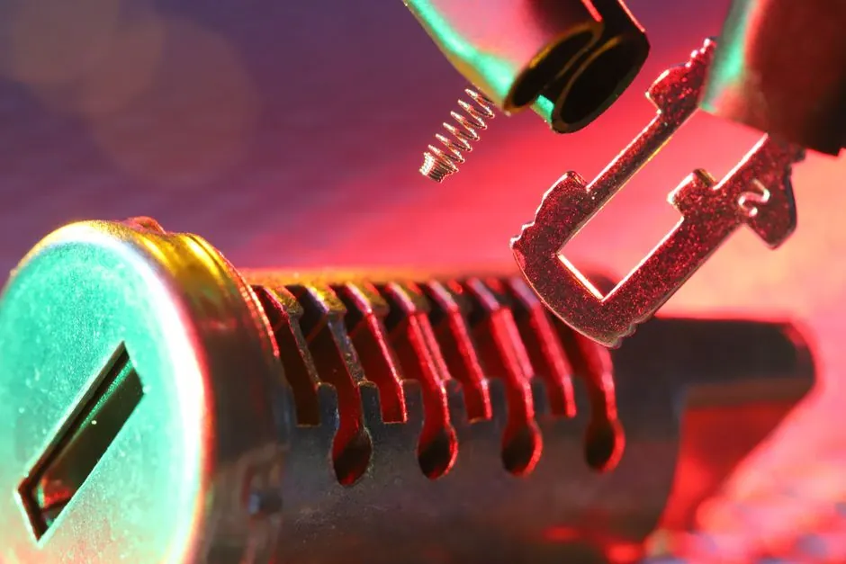
In die casting, the undercut release method is a die-architecture decision, not a detail: angle pin (cam pin / horn pin) slides are purely mechanical, driven by the press opening stroke through an angled pin engaging a slide block, while hydraulic core pulls use a cylinder powered by the machine's hydraulic circuit to drive the slide independently of die opening distance [S1][S2].
The two systems trade off against stroke length, available force, maintenance burden, and how much of the die casting machine's platen travel must be reserved for slide actuation, and that trade-off sets whether a die is built around the slide or the slide is built around the die [S1][S5].
Operating Principle and Force Path
Angle pin slides convert the vertical opening motion of the die into horizontal motion through a pin set at typically 15 to 25 degrees; springs hold the slide in the retracted position, and a lock block seats against the slide on die close to clamp it for the shot [S2]. A steeper pin angle raises the horizontal force the pin can apply to the slide, but it shortens the horizontal stroke obtainable from a given die-open distance [S3].
Hydraulic core pulls use a double-acting cylinder actuated by the machine's hydraulic supply: the cylinder advances the slide into position and locks it before injection, then retracts it before die open, independent of the die stroke [S1][S5]. Because the cylinder supplies force directly, it is not bound by the trigonometric limit that constrains angle pins, and a hydraulic lock can maintain 100 percent of its preload at zero hydraulic PSI when paired with a mechanical lock element [S2].
Stroke, Force, and Mass Limits
Horn pins work well when the required slide travel is small: the pin must grow roughly as 1/sin(theta) for every millimetre of horizontal stroke, so a 20 degree pin delivering 20 mm of horizontal travel needs around 58 mm of pin length and a matching increase in die-open distance [S1][S3]. Once slide travel and slide mass rise, the mechanical force available at the pin interface drops, accelerating wear on the pin, slide block, and the slide retainer [S1].
Hydraulic cylinders decouple slide travel from die-open distance entirely: the cylinder rod travels horizontally without requiring the die casting die to open further, and the cylinder can apply orders of magnitude more force than an angle pin of comparable envelope [S1]. This makes hydraulic core pulls the standard choice for long-stroke slides, large slide mass, multiple slides in one die half, and slides that must coexist with extensive conformal cooling [S1][S5].
Decision Matrix: Four Criteria Side by Side
On cost, angle pin slides win outright: no cylinder, no hydraulic plumbing, no proximity switches, lower build cost and lower spare-parts inventory [S1][S5]. On stroke length, hydraulics win, with stroke limited by cylinder selection rather than die-open geometry [S1]. On applied clamping force on the slide during injection, hydraulics with a mechanical lock win, holding full preload even if system pressure droops to zero [S2]. On maintenance, angle pins are simpler but wear items (pin, slide gib, wear plate) are still consumables; hydraulics add a cylinder, seals, lines, and connectors that are more expensive to service but largely standardised [S1][S2].
For a gravity die casting machine running a simple two-slide cover plate, angle pins are the rational default; for a high-cavitation automotive structural part on a magnesium die casting machine or aluminum die casting machine with five slides and aggressive cooling, hydraulics with mechanical locks are the rational default [S1][S4].
Die Design and Build Consequences
Designing an angle pin slide is highly technical and time-consuming because the engineer must calculate compound angles, machine angled pin bores, and verify that the die-open distance leaves enough pin engagement at full slide retraction [S4]. Designers typically machine locating features with a tooling ball to position the angle pin bore, and surface nitriding is commonly applied to the slide body and pin to slow wear [S2][S3].
Hydraulic core pulls shift complexity from geometry to plumbing: the die set must route hydraulic lines, manifold them to a control valve on the machine platen, and integrate proximity switches for slide-position verification before the machine allows the next shot [S1][S2]. The die casting machine itself must provide the hydraulic pressure and the safe-state lock logic, and dies that use hydraulic slides for undercut release generally run on machines that are already hydraulically equipped for core pulls, ejector boost, and intensification [S1][S5].
When to Specify Each Method
Specify angle pin slides when the undercut depth is small, the slide mass is low, the part volume does not justify hydraulic plumbing cost, and the foundry is set up for mechanical slides [S1][S5]. In short-run aluminium or zinc work on a gravity die casting machine, angle pins remain the most common and versatile slide mechanism because the press opening drives the motion and no external power is needed [S2].
Specify hydraulic core pulls when slide travel is long, multiple slides share the die, slide mass is high, the casting has large undercut areas, or the die must accommodate conformal cooling that consumes space normally used for mechanical slide linkages [S1][S5]. A practical rule of thumb from the field: once a slide travel exceeds roughly 30 to 50 mm or a slide mass pushes the available mechanical force margin thin, switching to a hydraulic cylinder becomes both simpler and more reliable than stretching an angle pin [S1][S3].
Common Failure Modes and Maintenance Signals
Angle pin slides fail by pin galling, slide gib wear, and lost motion at the lock block; symptoms include flash at the undercut, drift in part dimensions, and audible chatter at die close [S1][S2]. Hydraulic core pulls fail by seal leakage, hose fatigue at the platen transition, and drift in proximity-switch timing; symptoms include slow slide response, position-sensor faults, and hydraulic-fluid contamination in the die-lube circuit [S1][S2][S5].
Both systems require periodic inspection of wear surfaces, but a hydraulic slide returns higher diagnostic value through its position sensors and pressure gauges, which is one reason hydraulics pair naturally with data-driven process monitoring on a modern die casting machine [S1][S2].
Selection Rules Codified From Shop Practice

Use angle pins when the slide is small, the stroke is short, the part program is cost-driven, and the foundry prefers a purely mechanical die [S1][S5]. Use hydraulics when the slide is large, the stroke is long, multiple slides interact, the cycle must run fast, or the part program is high-volume and amortises the hydraulic infrastructure [S1][S4].
For a related perspective on cost-driven die decisions, see Aluminum Die Casting Part Cost Per Kg: Driver Breakdown; for the machine-side view of tonnage and tie-bar loading, see Tie-Bar Strain Monitoring on Aluminum Die Casting Machines: Tonnage Verification Methods; and for the upstream hydraulic supply that drives any hydraulic core pull, see HPU in a hydraulic circuit diagram: definition, components, and reading rules. Track the next die quote against two numbers: required slide stroke in millimetres, and slide mass in kilograms; if the second number pushes the angle pin force margin thin, plan a hydraulic conversion before the die is cut, not after the first wear failure.