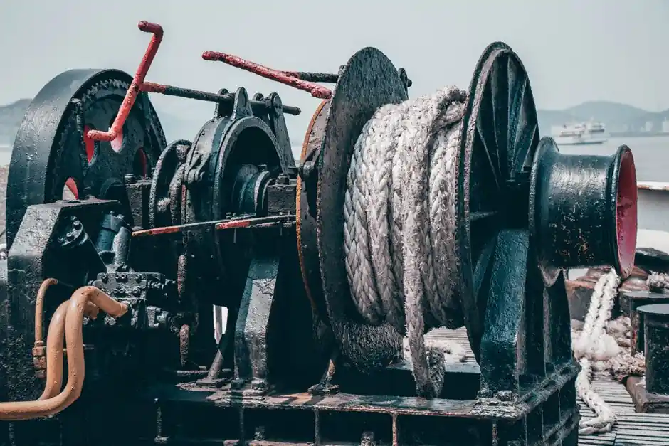
An HPU label on a hydraulic circuit diagram denotes a Hydraulic Power Unit, the self-contained assembly that converts mechanical shaft power from an electric motor or diesel engine into pressurised hydraulic flow [S1][S3].
The symbol groups a prime mover, a hydraulic pump, a fluid reservoir, suction and pressure lines, relief valves, and filtration, and its single boundary box tells the reader that everything inside is built and warranted as one skid [S2][S4].
What the HPU block actually contains
The minimum functional content of an HPU is three sub-blocks: a prime mover, a pump, and a reservoir, exactly the trio Supreme Integrated Technology lists as the foundation of any power unit [S3]. On the schematic, the reservoir is drawn as an open or vented tank, the pump as a circle with a filled arrow for fixed displacement or a diamond for variable, and the prime mover as a circle with an M or E marking inside the HPU boundary [S5]. Fast Flow Pumps' product range illustrates how widely that inner pump set varies in practice, with electric units from 30 HP up to 150 HP and diesel units climbing from 25 HP to 550 HP within one manufacturer's HPU family [S2].
A gear pump on the HPU drawing usually shows only suction and pressure ports, while a load-sensing piston pump will also carry a case drain line and one or two pilot lines for the load-sense network, a distinction that dictates how many external ports the HPU boundary has to expose [S4].
How the HPU label differs from neighbouring hydraulic symbols
An HPU block is not the same as a hydraulic actuator symbol. On ISO 1219 style schematics, cylinders and motors are drawn as the work-performing element with a piston, vane, or gear icon, while the HPU is upstream, drawn as a dashed or solid rectangular boundary containing the energy source [S5][S7]. Pressure-control, flow-control, and directional-control valves sit on the lines between the HPU and the actuator, not inside the HPU block, except for the pump-internal relief valve which is conventionally shown inside the HPU boundary on mobile schematics [S4].
On a circuit diagram, the HPA acronym is sometimes seen next to the HPU: HPA is the Hydraulic Pulsation Absorber, a bladder- or piston-type accumulator used either as a shock absorber on the HPU outlet or as a pressure pulsation damper on the pump line [S7]. Confusing HPU and HPA on a drawing leads to a missing pulsation study and premature pump seal failure, so the two should be read as separate items even when they share a line segment.
Reading HPU sizing cues on the schematic
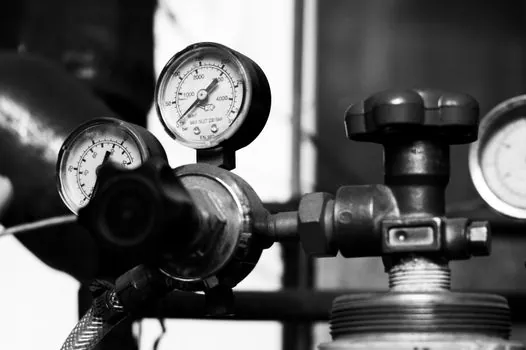
Reservoir volume on the HPU drawing is a hidden specification: the rule of thumb widely used by power-unit builders is to size the tank to at least 3 times pump flow, ideally 5 times, which translates into extra fluid dwell time for cooling, particle settling, and air release [S4]. Each multiple of pump flow adds roughly one minute of dwell time, and the same large surface area that lets contaminants settle also radiates heat to ambient, so a tall L-shaped tank drawn next to the HPU is a deliberate thermal choice, not packaging waste [S4].
Working pressure of an HPU on industrial schematics typically lands between 200 bar and 420 bar (roughly 3,000–6,000 PSI), and Fast Flow Pumps publishes a 6,000 PSI (about 414 bar) ceiling for its custom HPU line up to 600 HP and 200 GPM, a band that covers most mobile and stationary industrial duties [S2]. For higher-pressure test rigs, the HPU is often paired with an intensifier block drawn immediately downstream, which is a separate component, not part of the HPU [S1].
Selection criteria the schematic reveals
The HPU box on a drawing carries four decision layers: prime-mover type (electric or diesel), pump family (gear, vane, piston), reservoir geometry (vertical, T, or L shaped), and conditioning stack (filtration, heat exchanger, gauges) [S1][S4]. Electric HPUs dominate factory and indoor service where mains power is reliable, while diesel HPUs are specified for remote, mobile, or hazardous-area work where grid power is unavailable [S3]. Filtration and cooling equipment is shown on the return line inside the HPU boundary and is sized to keep ISO 4406 cleanliness codes in the 18/16/13 to 22/18/15 band typical of industrial hydraulic systems [S1][S4].
For Zone 1 and Zone 2 hazardous-area service, the HPU drawing will carry an ATEX/IECEx marking on the nameplate callout, and the motor enclosure is changed to Ex d or Ex e, which is documented at the schematic boundary rather than re-explained inside it [S1][S3].
Comparison: HPU against other hydraulic energy sources on a schematic
Three main options sit upstream of a hydraulic cylinder or hydraulic motor on a circuit diagram, and the HPU is only one of them. Against an integral pump built into the actuator, an HPU is louder and floor-space hungry but lets one energy source drive multiple actuators and centralise maintenance. Against a pneumatic supply, an HPU delivers incompressible fluid and roughly ten times the power density at typical 200–350 bar working pressure, at the cost of a return-line leak path and oil-cleanliness discipline. Against an electric direct-drive actuator, the HPU wins on force density and overload tolerance but loses on energy efficiency, since every hydraulic conversion step costs 10–25 percent of input power as heat. The HPU is the right choice when multiple high-force actuators must be coordinated from one source; a single-axis electric actuator is the right choice when a clean room, food-grade line, or sub-second precision loop is needed. [S1]
Common reading errors and limitations on HPU schematics
The most common misreading is to treat the HPU boundary as the noise and heat source only and ignore that pump case drain must be piped back to the reservoir below the fluid level, a rule that is easy to draw wrong and expensive to find at commissioning [S4]. Another trap is to assume an HPU symbol is a single pump, when in practice a power unit on a complex mobile machine is a fixed pump plus a load-sensing variable pump in tandem, drawn as two circles with a common shaft inside one HPU boundary [S4]. Air entrainment at the reservoir is a third failure mode that the schematic can hide: if the return line is shown entering above the low fluid level, the HPU will aerate the pump and shorten bearing life, regardless of how clean the filtration is [S1][S4].
Maintenance windows follow directly from the HPU layout: filtration on the schematic is shown as a stand-alone block with a differential pressure gauge so that element change-out does not require draining the reservoir, and the HPU should be specified with the serviceability of the L-shaped tank in mind rather than the cheapness of the vertical tank [S4]. For a process engineer cross-checking whether a vendor's quoted HPU matches the schematic, the hydraulic system reference page is the natural starting point before approving the drawing.
Track these signals before signing off a hydraulic circuit diagram that contains an HPU block: the prime-mover rating in kW or HP at the duty point, the pump family and its displacement in cc/rev, the reservoir volume in litres and how it is shaped on the drawing, and the working pressure shown on the relief valve callout. A second pass should confirm that case drain and load-sense pilot lines return to the correct ports, that filtration has a DP gauge on the schematic, and that the ATEX/IECEx marking is present if the HPU sits in a classified area. For a related cross-discipline read on how the same pressure-and-flow logic shows up in a different actuator family, see fluid coupling selection for automotive production lines, which applies analogous prime-mover sizing rules to hydrodynamic drives.