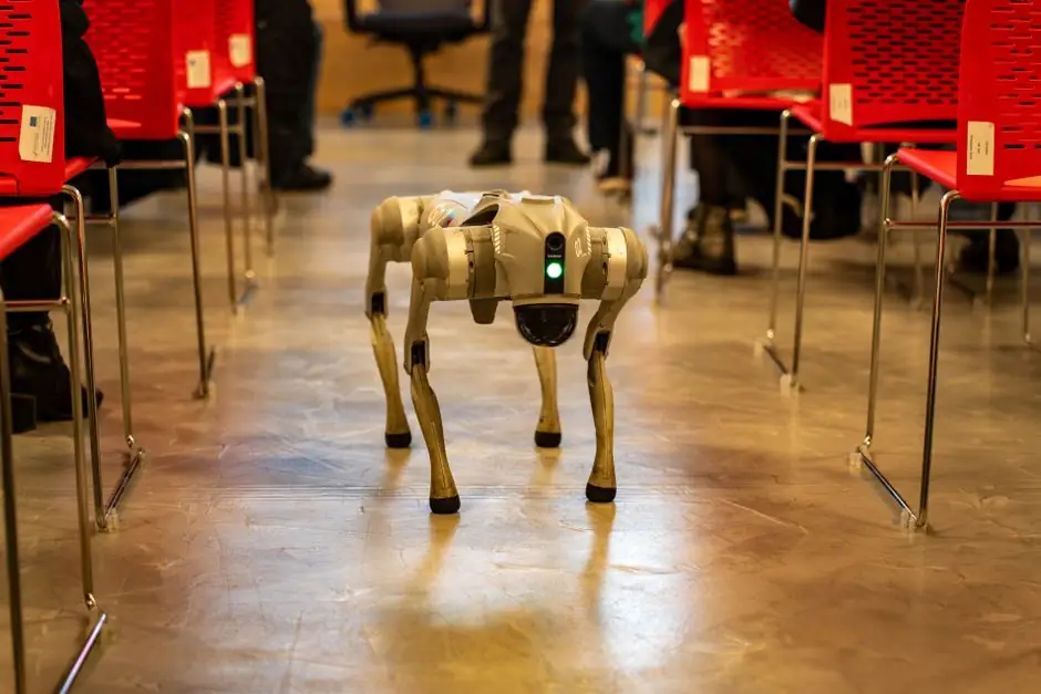
ANSI/A3 R15.08-1-2020 (R2026) is a reaffirmed 122-page safety standard for Industrial Mobile Robots (IMR), governing hazard identification, risk reduction, design verification, and information for use on the mobile platform itself [S1][S3].
Reaffirmed in 2026, R15.08-1 sits at the center of a three-part series, where Part 1 targets manufacturers of the mobile robot, Part 2 (R15.08-2-2023) covers system integration, and Part 3 covers user responsibilities, giving integrators a complete risk chain from chassis design to site operation [S2][S3].
Scope: AGV vs AMR vs IMR Type A, B, C
R15.08-1 draws a hard line between AGVs, which follow predefined guide paths (virtual or physical), and AMRs, which compute an obstacle-free path through free space using onboard sensors, and then bundles both into the broader IMR category defined in R15.08-2-2023 [S2].
Clause 1 of ANSI/A3 R15.08-2-2023 partitions IMRs into three classes: Type A (bare AMR platform, intended as a base for Type B or C), Type B (AMR with passive or active attachments such as roller tables, conveyors, or linear lifts, but no manipulator), and Type C (AMR or AGV base with a manipulator as the attachment) [S2].
For Type C units, R15.08 explicitly defers manipulator safety to R15.06, which requires PLd Category 3 or SIL 2 safety functions, mirroring the ISO 10218 / ISO 13849 architecture expected of fixed industrial arms [S2].
Risk Assessment: Four-Tier Severity and a Five-Step Reduction Process
R15.08-1 uses a four-tier severity scale, S1 minor through S4 fatal or life-threatening, finer-grained than the two-tier S1/S2 in ISO 13849-1, which lets risk graphs resolve borderline cases more accurately [S4].
The reduction process follows the classic hierarchy: elimination by design, substitution and engineering controls, protective devices, administrative controls, and finally validation with continuous improvement, with intentional interactions (teaching, loading, tool change), unintentional interactions (pedestrian contact, path conflict), environmental hazards (floor grates, tight corners), and foreseeable misuse (unauthorized software changes, localization loss) all listed as required inputs to the hazard list [S4].
Annex A gives an informative list of significant hazards, Annex C specifies the parameters and thresholds for required safety function performance, and Annex F adds a normative stability test regime, so the 2020 text already ships a usable verification scaffold rather than a purely narrative checklist [S3].
Design Requirements: Stability, E-Stops, and Safety-Rated Monitored Stop

R15.08-1 Chapter 5 mandates safety-rated monitored stop, emergency stop protocols, stability monitoring, and the system-architecture expectations for an IMR, with redundant controllers, fault detection, and independent monitoring all expected on the safety control path [S4].
For personnel detection, the standard expects PLd (ISO 13849) performance on the primary safety control function, the same level called out in ISO 3691-4, which makes dual compliance achievable when the same safety laser, bumper, and safety PLC are reused [S4].
Loss of localization is treated as a foreseeable misuse, not an edge case, so the standard expects the safety layer to remain functional even when navigation confidence drops, which in practice pushes designers toward independent safety PLCs decoupled from the fleet manager [S4].
Comparison: R15.08-1 vs ISO 3691-4 vs B56.5
ANSI/ITSDF B56.5 historically covered AGVs, ISO 3691-4 covers driverless industrial trucks globally with PLd-rated personnel detection and a three-zone model (operating, restricted, confined), and R15.08 covers IMRs with manipulator support and a finer four-tier severity scale, the three documents now form a complementary set rather than competing ones [S4].
CE marking in Europe leans on ISO/IEC/EN standards, so a CE-marked IMR typically cites ISO 3691-4 plus ISO 10218 for the manipulator, while a North American unit cites R15.08 plus R15.06, and as of 2025 ISO 10218 explicitly defers to ISO 3691-4 for mobility behaviors in mobile manipulators, sharpening the global alignment picture [S4].
For a side-by-side view, the most relevant decision criteria are: target region (EU vs North America), mobility model (predefined guide path vs free-space navigation), manipulator presence (none, attachment, full arm), and severity scale (two-tier S1/S2 vs four-tier S1–S4), see how these line up in the AGV compliance breakdown.
System Integration: R15.08-2 Zones, Traffic, and Fleet E-Stops
R15.08-2-2023 takes the manufacturer-compliant robot from Part 1 and places it into a working environment, covering deployment design, traffic management, facility safety-system coordination, and multi-robot coordination strategies [S2][S4].
Part 2 is expected to specify admissible mobile-robot speed based on the presence of safety sensors and operator escape clearances, parameters that integrators currently derive from ISO 3691-4 zone management, where operating zones allow full detection and restart, restricted zones apply speed limits and warnings, and confined zones require physical barriers and interlocks [S3][S4].
Fleet-level safety adds a coordination layer on top of the per-robot safety stack: coordinated E-stop response, traffic orchestration across robots, and compatibility with fleet manager software, with the AGV and mobile crane operational context and the broader mobile crane safety baseline both useful reference points when the same warehouse mixes IMRs with other moving equipment.
Verification, Validation, and Information for Use
Annex D of R15.08-1 is normative for verification and validation of the risk-reduction measures, which is the section most often skipped in practice and the one most often cited in incident reports, so engineers should treat the V&V matrix as a deliverable, not a checkbox [S3].
Information for use in Chapter 8 covers markings, labels, and the user documentation that has to ship with the robot, including the residual risks the manufacturer could not eliminate by design, and these residual-risk disclosures feed directly into the end-user risk assessment required by Part 3 [S3].
On the machine-safety side, R15.08 does not stand alone: it is layered on top of the general machine-safety framework and the safety certification chain, with fire-safety integration handled at the facility level once the robot itself is compliant.
Who Should Cite R15.08, and When It Is the Wrong Standard
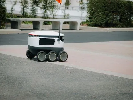
R15.08-1 is mandatory language for any IMR manufacturer selling into North America, and is the right reference for system integrators building mixed-attachment cells (Type B) and mobile manipulators (Type C) on an AMR or AGV base [S1][S3].
It is the wrong tool for pure driverless forklift deployments, where ANSI/ITSDF B56.5 and ISO 3691-4 still govern, and for fixed industrial arms, where R15.06 / ISO 10218 apply without the mobile-platform overlay [S4].
End users operating, not building, the IMR should pair the R15.08-1 manufacturer declarations with R15.08-3 once published, and until Part 3 lands they can fall back on ISO 3691-4 fleet integration guidance, an approach consistent with the underride-lift vs conveyor-top AGV selection logic and the AGMA vs ISO gearbox choice used elsewhere in a typical cell.
The next nodes worth tracking are the publication of R15.08-3 (user responsibilities), the closure of the EN ISO 10218 / ISO 3691-4 gap work on manipulators on mobile platforms, and any CENELEC harmonization that would give R15.08 a formal European counterpart, since as of the 2026 reaffirmation no EN or ISO standard has an identical scope [S2].