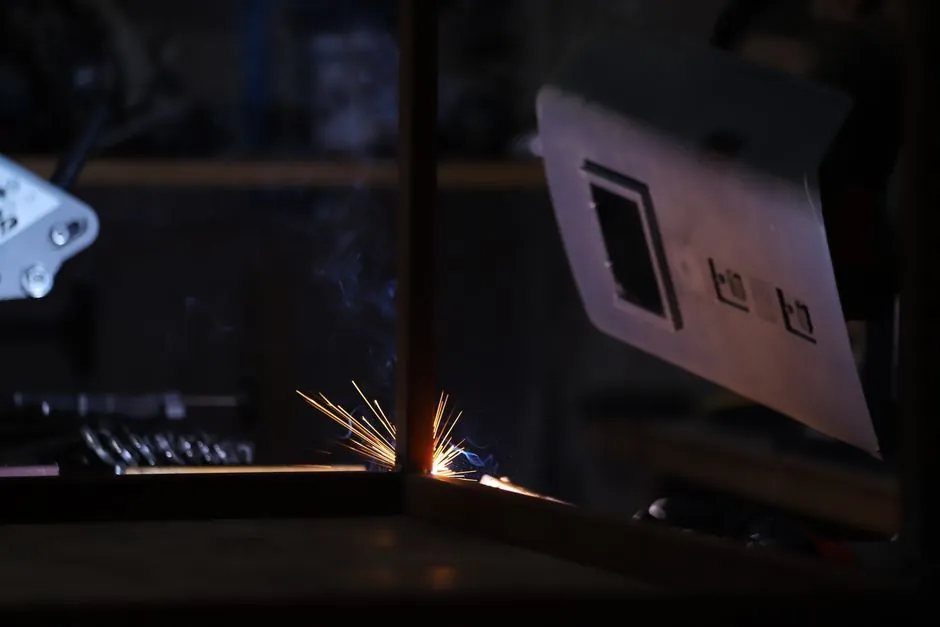
Open-circuit voltage on conventional arc welding machines measures between 50-80 V at the electrode holder when the machine is energised but no arc is established [S3]. For AC electric arc welding specifically, the no-load voltage is commonly specified across a 50-90 V band, the answer range used in production-engineering practice questions [S4]. Once an arc is struck and current begins to flow, terminal voltage collapses from the no-load level to an operating arc voltage that typically runs 20-40 V depending on process, electrode, and current setting [S3].
Reputable inverter-based MMA/stick welding power sources are designed to deliver OCV of 50 V or higher so that arc initiation remains reliable across common electrode classes [S1][S2]. For DC arc welding, the open-circuit voltage must be at least 30-35 V, while AC arc welding requires no less than 50-55 V to break down the gap and sustain a stable arc [S4]. Higher OCV values make arc striking easier, particularly with cellulosic electrodes and out-of-position work, where the additional potential helps overcome the higher ionisation threshold of the cellulose-coated rod [S3].
OCV Definition and How It Differs from Arc Voltage
Open-circuit voltage, also called no-load voltage, is the potential difference measured between the electrode and the workpiece with the machine powered on but no current flowing in the circuit [S3]. It is the "waiting voltage" the power source holds across the electrode holder and the work clamp while the welder is idle. The OCV is set by the transformer's turns ratio in conventional machines, and by the boost converter / inverter output stage in modern IGBT-based designs, with the value typically landing between 50 V and 80 V on shipped product [S3].
When the operator strikes an arc, current begins to flow and the terminal voltage drops sharply from the no-load level to the operating arc voltage, usually 20-40 V for most manual processes [S3]. This drop is governed by the power source's volt-ampere curve and the dynamic resistance of the welding arc itself, not by a separate "welding voltage" setpoint. OCV therefore matters mostly at the moment of arc initiation: it provides the initial potential needed to ionise the air gap, after which the arc takes over at its self-sustaining lower voltage. For a deeper look at how MMA/stick welders are defined as a process, see the reference entry on shielded metal arc welding.
Selection Criteria: Where in the 50-90 V Range Your Spec Should Land
Selection of an OCV target begins with the welding process: AC transformer machines are commonly designed around 50-90 V OCV, while DC inverter machines often sit in the 50-80 V band with adjustable hot-start lift [S3][S4]. The next criterion is electrode class: cellulosic rods (AWS E6010/E7010) demand higher OCV than rutile (E6012/E7012) or basic (E7018) coatings because of their higher arc-striking resistance [S3]. Work environment matters too: confined spaces, wet conditions, and high operator contact with grounded metal push the design toward Voltage Reduction Devices (VRDs) that clamp OCV below the conventional 50-80 V band until the arc is established [S3].
For typical site fabrication, machines that deliver OCV of 50 V or more are accepted as offering "good" arc characteristics and are the design floor for reputable inverter MMA welders [S1][S2]. Industrial heavy-stick work on cellulosic pipe-welding rods often targets the upper end of the band, closer to 70-80 V, to ensure consistent arc strike in field conditions. Light-duty DIY and entry-level inverter units frequently sit at the lower end of the 50-80 V range, trading some strike margin for a safer touch voltage on the electrode. Refer to the arc welder duty cycle reference for how OCV, current rating, and thermal limit interact on the same nameplate.
Process and Power-Source Comparison: AC vs DC vs Inverter OCV Behaviour
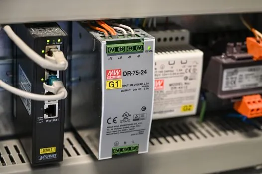
AC arc welding sets, typically transformer-rectifier or pure transformer designs, are specified across the 50-90 V OCV range, with the higher end preferred to compensate for the zero-crossing loss of AC arcs and the harder restrike after each half-cycle [S4]. DC inverter machines concentrate in the 50-80 V band and add electronic hot-start, where the inverter briefly boosts voltage above the steady OCV to initiate the arc, then drops back to the running arc voltage once current is established [S3].
Conventional transformer-rectifier machines tend to have fixed OCV close to the upper end of the 50-80 V range and are heavier for the same current rating because the magnetic components set the no-load voltage. Inverter machines achieve the same 50-80 V OCV from a much smaller high-frequency transformer, trading simple magnetics for more complex control electronics and IGBT switching stages. On the safety axis, modern inverter units often integrate a VRD that holds the output below approximately 24-30 V in the open-circuit state and only releases the full 50-80 V OCV when the electrode touches the workpiece, a feature less common on legacy transformer sets.
Operator Use Cases: Matching OCV to Electrode, Position, and Site Conditions
In field pipe welding with E6010 cellulosic electrodes, operators rely on the upper end of the 50-80 V OCV band to strike consistently on dirty or cold pipe, with the higher no-load voltage overcoming the cellulose coating's high ionisation threshold [S3]. For shop fabrication of structural steel using E7018 basic rods, the lower end of the band, around 50-60 V, is usually sufficient because the basic coating strikes more easily and the work is in flat or horizontal positions. For thin-sheet work and out-of-position TIG root passes, lower OCV combined with lift-arc or HF start is preferred to avoid tungsten contamination and arc blow.
Environmental use cases drive the safety case for OCV reduction: wet-site ship repair, tank work inside confined spaces, and any welding where the operator is in contact with grounded metal all raise the electric-shock risk from the 50-80 V no-load level [S3]. In these scenarios, a VRD-equipped inverter that clamps OCV to a touch-safe value until the arc is struck is the typical specification. For more on the engineering trade-offs of related industrial power-conversion hardware, see the medium-voltage VFD reference, which covers similar inverter-stage design constraints.
Limitations, Safety Constraints, and Failure Modes
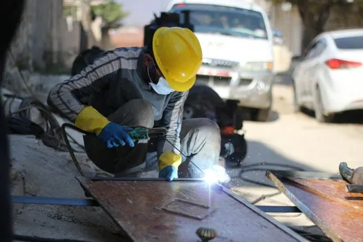
The primary hard limit on OCV is operator electric-shock safety: the 50-80 V no-load level, while below the 100 V threshold often cited for DC "extra-low voltage," is still hazardous in wet conditions, confined spaces, and where the operator is well-coupled to grounded metal [S3]. Risk increases significantly in damp environments because skin resistance drops and the body becomes a viable current path from electrode to ground. Cellulosic and basic electrodes that demand higher OCV, toward the 70-80 V end of the band, therefore carry the highest touch-risk and are the strongest case for VRD retrofit on existing transformer sets.
Failure modes tied to OCV include difficult arc striking when the no-load voltage has sagged below the electrode class requirement, typically a sign of failing boost capacitors in inverter machines or a weak mains supply on transformer sets. Excessive OCV, by contrast, accelerates tungsten erosion in TIG and increases electromagnetic interference on nearby electronics. Modern machines therefore ship with OCV clamped inside the 50-80 V window for conventional MMA and 50-90 V for AC sets, and rely on the electronic hot-start to deliver a transient boost above steady OCV only at the moment of arc initiation [S1][S2][S3][S4].
Standards Anchors and What Buyers Should Verify on the Nameplate
When evaluating an arc welding machine, the key OCV figures to confirm on the specification sheet are the no-load voltage in volts (typical band 50-80 V for conventional MMA, 50-90 V for AC sets), whether the unit has a VRD and its clamped open-circuit value, and the process compatibility (MMA, TIG, MIG) at the stated OCV [S1][S2][S3][S4]. Reputable inverter MMA welders are designed around an OCV of 50 V or higher; units below that floor should be treated as trade-only or entry-level and may struggle with cellulosic electrodes. For buyers cross-referencing inverter topology trade-offs, the welding and cutting tool reference collects the adjacent process spec data.
Trackable next signals to watch: vendor datasheets explicitly publishing VRD-clamped OCV values (currently often withheld as a generic "anti-shock" feature), and any tightening of the 50-90 V AC OCV band in future revisions of the relevant welding safety standard, both of which would shift the design floor quoted above.
The underlying component specifications are covered under arc welder.