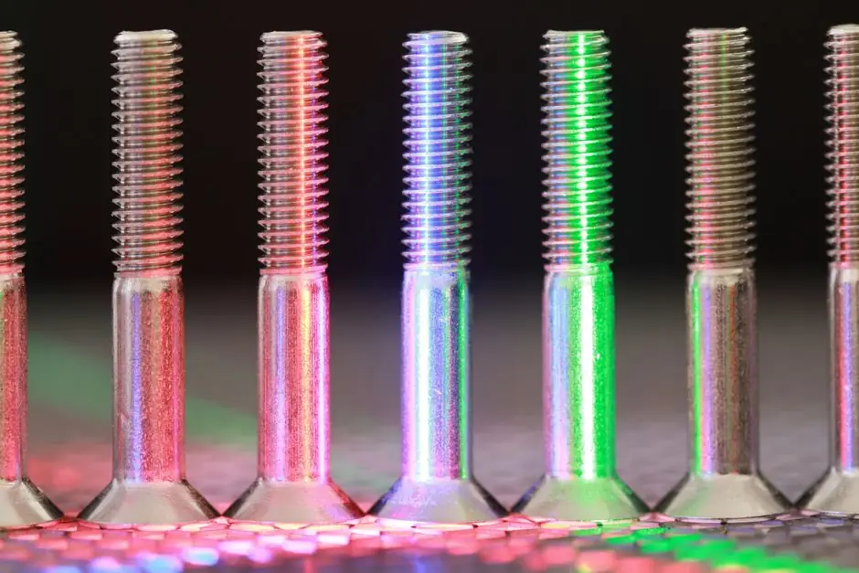
Backlight, dome, and coaxial lighting use three distinct geometries to produce silhouettes, diffuse surface contrast, and on-axis feature visibility [S1][S2][S3].
Backlight suits edge detection and dimensional inspection, dome light reduces harsh reflections on curved or uneven surfaces, and coaxial light targets surface detail near the camera axis [S1][S5].
Lighting Geometry Defines the Detectable Feature
Backlighting places the light behind the object, producing a silhouette for edge detection and dimensional checks [S1]. A dark-field backlight is appropriate for picking up defects in transparent objects.
Dome lighting distributes light through a broad surface around the working area, while coaxial lighting aligns illumination with the camera axis [S1][S3]. Flat diffuse lighting combines dome and coaxial diffuse characteristics, producing more off-axis light than the on-axis geometry alone [S2].
The standard selection framework treats geometry, pattern or structure, wavelength, and filters as four image-contrast controls [S2]. This matters because each geometry creates a different image representation and therefore exposes a different set of surface features [S6].
Backlight Selection for Edges and Dimensions
Use a backlight when the required measurement is an outline, edge position, gap, width, or other dimensional feature [S1]. Backlighting is useful for producing silhouettes and highlighting dimensional features.
Backlighting is not the first choice for every surface defect. A part that is transparent or translucent may transmit the light rather than create a clean silhouette, while a reflective front surface can contribute unwanted camera-side highlights. Transparent-object defect inspection is better associated with dark-field backlight geometry [S7].
Field of view, working distance, and mounting space determine the usable backlight size and placement [S4]. A change in working distance alters the illuminated area, delivered intensity, and effective lighting angle, so an assembly validated at one working distance should not be assumed valid after a camera or fixture adjustment [S4].
Dome Lighting for Diffuse Surface Contrast
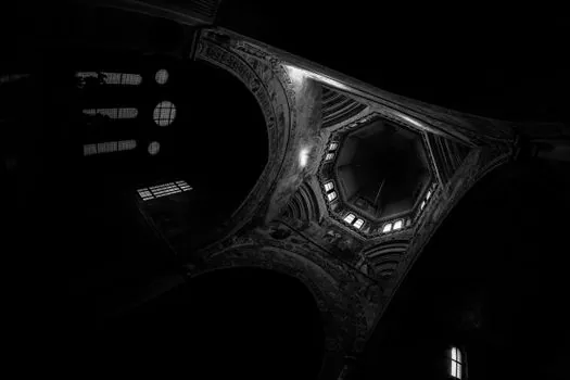
Dome lighting is used when broad, diffuse illumination is needed across a surface [S3]. Its form factor surrounds or sits above the inspection region, reducing the directional contrast that can create glare on smooth or curved parts [S4].
Dome light is a practical choice when the target is a broad surface appearance rather than a silhouette or a small directional reflection. This includes curved components and uneven surfaces where a hard bright-field source may create confusing highlights [S4][S5].
Working distance remains a design variable for dome systems because it changes the illuminated footprint and intensity reaching the part [S4]. The housing also must fit the camera and object arrangement without obstructing the required field of view.
Coaxial Lighting for On-Axis Detail
Coaxial lighting aligns the illumination with the camera's optical axis, producing illumination that is close to the camera's viewing direction [S1][S3]. It is therefore relevant when the inspection depends on light reflected from a surface feature toward the lens.
The lighting reference separates coaxial lighting from coaxial diffuse lighting, while Cognex identifies coaxial on-axis diffuse illumination as a distinct technique within its five-part classification [S5][S7].
Coaxial light can be effective for flat, reflective components when the desired defect is aligned with the camera's viewing direction [S5]. Its limitation is geometric: the axis shares the same direction as the camera, so reflections from nominally flat areas can also dominate the image. Dome or off-axis approaches are more suitable when reducing surface glare is the primary objective [S2].
Side-by-Side Selection Criteria
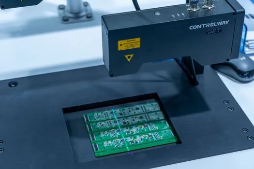
Backlight wins on silhouette and dimensional contrast, dome wins on diffuse appearance and glare reduction, and coaxial wins on axis-aligned surface detail. The trade-off is task type, not brightness alone: backlight measures the boundary, dome measures broadly distributed surface response, and coaxial measures direction-dependent reflection [S1][S2][S5].
For moving parts, lighting must cover the inspection area despite product position and orientation variation [S4]. Dedicated machine-vision lighting also provides a controllable signal independent of operator and overhead illumination. Cognex states that a dedicated, high-intensity light at short exposure can keep the image stable when room lighting changes, while changing a facility from fluorescent to LED can alter the camera's view through wavelength and color-temperature shifts [S5].
Color is not a substitute for geometry. Wavelength still has to match the target defect and camera response, and the practical lighting design method combines geometry, pattern, wavelength, and filters [S2]. For the vision light source, begin with the feature, then use camera exposure and geometry as downstream variables rather than trying to recover missing contrast through image processing.
Application Fit and Failure Modes
A backlight inspection can fail through poor object alignment, contamination, insufficient contrast, or field-of-view mismatch. Dome lighting can fail when the housing obstructs the camera, the working distance changes, or the diffuser is positioned so that a dominant specular reflection remains. Coaxial inspection can fail when the feature does not redirect sufficient light toward the camera or when broad surface glare masks the target [S1][S4][S5].
Surface roughness changes the interpretation of every geometry. Specular surfaces redirect light narrowly, diffuse surfaces spread it, and transparent materials transmit or scatter it. That is why the design must examine object-light interaction and ambient contribution rather than select a fixture from the camera field of view alone [S2].
A dedicated light also removes an avoidable failure mode: uncontrolled facility lighting. The published lighting guidance notes that operator lights may switch independently between shifts and that changing fluorescent fixtures to LED can shift wavelength and color temperature, altering the captured image [S5]. This is a reproducibility problem, not a camera-resolution problem.
Engineering Selection Sequence
Begin with 4 measurable inputs: the feature of interest, object surface, required field of view, and available working distance [S4]. Add the object-light behavior, ambient light, camera spectral response, and required throughput before fixing the fixture geometry [S2].
For edge or dimensional inspection, specify a backlight and validate silhouette stability across the full presentation tolerance. For curved or uneven surfaces where highlights interfere, trial dome lighting and compare image uniformity. For a flat feature that sends light back toward the lens, evaluate coaxial lighting, then test whether surface reflection overwhelms the defect [S1][S5].
The next validation step is a controlled image trial using representative production parts, all expected part positions, and the intended camera exposure. Hold fixture position, working distance, camera settings, and illumination level fixed while ambient conditions change. That converts a lighting preference into a measurable contrast and robustness decision [S2][S5].