A Li-ion cell's nameplate energy density is bounded less by cathode active material than by how the electrolyte is mixed, dried and metered: typical production-grade LiPF6 in EC/EMC/DMC carries water below 20 ppm and HF below 50 ppm to keep SEI formation reproducible on graphite and silicon-blend anodes [S2].
Electrolyte manufacture is a four-step chain — salt synthesis (LiPF6, LiFSI, LiTFSI), solvent purification, additive dissolution, and final blend with moisture control — all run under dry-room dew point of -40 °C or lower before the liquid is fed into cell filling lines used across pouch, prismatic and cylindrical formats [S2]. The article that follows maps the unit operations, the decision criteria for salt and additive selection, and the inline QA stack that determines whether a 100 Ah prismatic cell passes formation cycling.
Electrolyte Function, Composition Window and Why It Is Process-Critical
The lithium-ion cell is a sandwich of two electrodes, a porous polyolefin separator, and a liquid or gel electrolyte whose job is dual: conduct Li+ between anode and cathode while remaining electronically insulating, and form a stable solid-electrolyte interphase (SEI) on first charge [S1][S2]. A standard 1 M LiPF6 in EC:EMC:DMC (1:1:1 v/v) with 1-3 wt% vinylene carbonate (VC) and 0.5-2 wt% fluoroethylene carbonate (FEC) additive package covers most graphite/NMC811 cells; deviations from that window change cycle life more than equivalent changes in cathode loading [S1].
Slurry-cast electrodes — still the dominant route for consumer and EV Li-ion production — leave residual moisture and binder residues that react with LiPF6 to form HF, which is why water content is the single most tightly controlled parameter upstream of the filling head, with typical industrial targets of less than 20 ppm H2O for high-nickel chemistries [S1][S2]. For lean-electrolyte Li-S architectures, electrolyte-to-sulfur (E/S) ratio has dropped from the 2018-era 15 µL mg-1 baseline toward 5 µL mg-1 or below, demanding even tighter moisture and polysulfide-shuttle control [S4].
Unit Operations: From LiPF6 Salt to Filled Cell
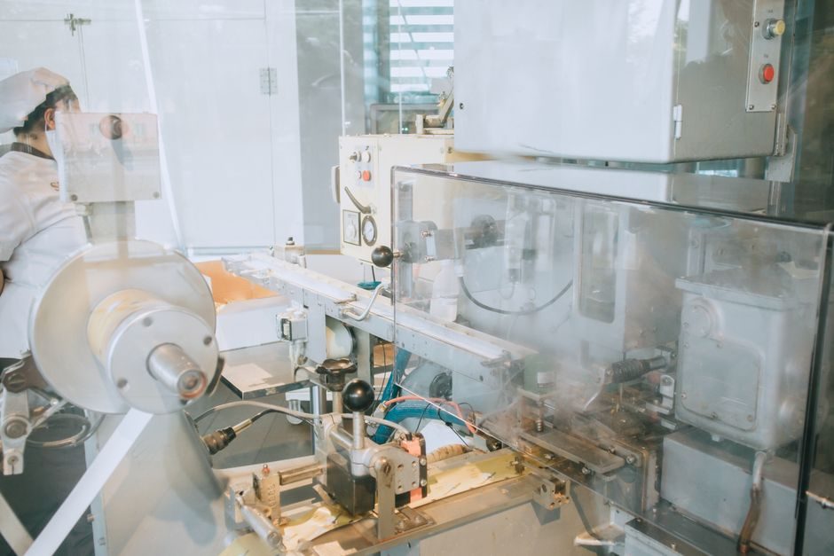
Electrolyte plants run four primary unit operations in series. (1) Salt synthesis: LiPF6 is made by reacting Li2CO3 or LiOH with HF and PF5 in butyl acetate or similar anhydrous solvent, then crystallised and dried to 99.9% purity; LiFSI and LiTFSI follow similar Li-cation metathesis routes with sulfonyl-fluoride intermediates. (2) Solvent purification: battery-grade EC, EMC and DMC are distilled and passed through molecular sieves to knock water down to single-digit ppm. (3) Additive dosing: VC, FEC, propane sultone (PS) and lithium bis(oxalato)borate (LiBOB) are weighed on precision balances inside the dry room, then dissolved in the base solvent. (4) Final blend and fill: the mixture is agitated in stainless or PFA-lined tanks under N2 blanket, sampled for moisture (Karl Fischer), HF (acid-base titration) and density, then pumped through industrial valve-controlled headers to cell-filling workstations where vacuum-assisted filling is followed by vacuum sealing [S2].
The dry-room envelope is the binding constraint. A 10,000 m2 cell assembly hall is typically held at -40 °C dew point (about 100 ppm absolute moisture) for Li-ion production, and high-nickel lines push that to -60 °C dew point (under 10 ppm) to suppress LiOH and Li2CO3 formation on NMC811 surfaces [S2]. Basler's line-scan and area-scan camera stacks — ace 2 X visSWIR for separator inspection and pylon-driven area scan for electrode alignment — sit in the same hall and act as the QA gate that rejects electrodes carrying >X ppm moisture residues before they ever meet electrolyte [S2].
Salt and Additive Selection: LiPF6 vs LiFSI vs LiTFSI on Decision Criteria
Salt choice is a four-criterion decision: ionic conductivity, thermal stability, aluminium-collector corrosion, and cost. LiPF6 remains the default — 25 °C conductivity around 10 mS cm-1 in 1 M EC/EMC, decent thermal stability up to ~60 °C in the cell, and passivation of aluminium at >3.7 V vs Li/Li+ — but its HF-generating hydrolysis drives the dry-room specification [S1][S2].
LiFSI delivers higher conductivity (about 12-15 mS cm-1 at 1 M in the same solvent mix), better thermal stability to 80 °C, and no HF generation, but corrodes aluminium at high voltage unless paired with LiPF6 at ≥30 mol%. LiTFSI has the highest conductivity and thermal robustness but is ruled out for high-voltage Li-ion by aluminium pitting unless used in Li-S or polymer-electrolyte contexts. The practical 2026 split for high-nickel EV cells: 70-90 mol% LiPF6 + 10-30 mol% LiFSI as the conductivity/stability bridge [S4].
Dry-Room and Inline QA Stack: What Catches a Bad Batch
Inline QA on an electrolyte line runs three layers. First, raw-material incoming: Karl Fischer titration for solvent moisture (<10 ppm target), ICP-OES for cation impurities in LiPF6 (Na, K, Ca each <1 ppm), and ion chromatography for sulfate and chloride by-products, with sample-loop flow governed by a flow meter on the auto-sampler sub-loop. Second, in-process: continuous density and conductivity probes on the blend tank, with a sub-loop auto-sampler pulling batches for full Karl Fischer and acid titration. Third, cell-level: formation cycling at C/20 with cumulative coulombic efficiency >99.5% on the first cycle, used as the ultimate pass/fail on a sampled-cell basis [S2].
Vision systems contribute at the upstream electrode/separator interface rather than the electrolyte tank itself: high-resolution inspection of separator foils for pinholes, of electrode alignment in prismatic windings, and of electrode edge raggedness that would draw extra electrolyte and starve neighbouring cells in the pack [S2]. For a closer look at how separator coating and inline QA interlock with electrolyte filling, see Separator Wet vs Dry Process; the matching Cathode Material Manufacturing piece covers the active-material half of the cell that the electrolyte must wet uniformly.
Solid-State and Dry-Electrode Adjacencies Reshaping 2026 Specifications
Two 2026-era shifts bear directly on the liquid-electrolyte plant. First, dry-electrode coating (no NMP solvent) cuts moisture residue to a fraction of slurry-cast levels, but then demands even tighter electrolyte water spec because any residual O-H groups on the dry cathode surface form HF on contact with LiPF6 [S1]. Second, sulfide and oxide solid-state electrolytes are moving from lab to pilot — typically Li6PS5Cl argyrodite or LLZO garnet — which removes the liquid tank entirely but introduces dry-room control of H2S and CO2, a different but overlapping hazard envelope.
For an architectural view of how 2026 solid-state lines are laid out and where dry-electrode coating slots in, Solid-State Battery Smart Manufacturing maps the line; meanwhile, the lean-electrolyte Li-S path is the closest analogue to a future where E/S ratio below 4 µL mg-1 becomes the new baseline [S4].
Failure Modes and Constraints Engineers Should Price In
The most common electrolyte-line failure modes are HF-induced separator delamination (driven by water >20 ppm), aluminium-collector pitting (driven by LiFSI over 70 mol% or over-voltage), and additive decomposition (driven by tank temperature >35 °C during VC or FEC dissolution). Each maps to a measurable upstream signal — tank thermocouple drift, Karl Fischer excursion, formation-cycle coulombic efficiency below 99.0% — that should trigger a hold rather than a release [S2].
The 2026 bottleneck is not chemistry but plant capacity: a 50 GWh cell factory consumes on the order of 4,000-6,000 tonnes of electrolyte per year, and the global LiPF6 supply chain is still concentrated in a handful of Chinese and Japanese producers. Engineers specifying a new line should plan dual-sourced LiPF6 and on-site LiFSI blending if high-nickel cells are in the product mix; a single-source salt qualification is a single point of failure the dry-room QA stack cannot rescue.
Sourcing, Standards and the Next Engineering Node to Watch
Battery-grade electrolyte specifications are not governed by a single IEC or ISO standard; instead, buyers reference a stack including GB/T 36276-2018 (China, Li-ion cells for energy storage), IEC 62133-2 (portable Li-ion safety), and OEM-internal specs that typically tighten water to <15 ppm and HF to <30 ppm. The 3D microlattice electrode work that underpins solvent-free additive manufacturing material routes is the upstream signal worth tracking: a fully dry, printed electrode would let a future cell factory shrink its dry-room envelope and reallocate footprint to packing rather than mixing [S1].
Trackable nodes for the next reporting period: published updates to GB/T 36276 thresholds, LiFSI pricing convergence toward LiPF6, and any disclosure of 5 µL mg-1 E/S ratio Li-S cells entering automotive qualification [S4]. For context on how the finished cell becomes a pack — and where electrolyte residuals are most likely to trigger field returns — see Battery Pack Smart Manufacturing and Battery Pack Process Flow.