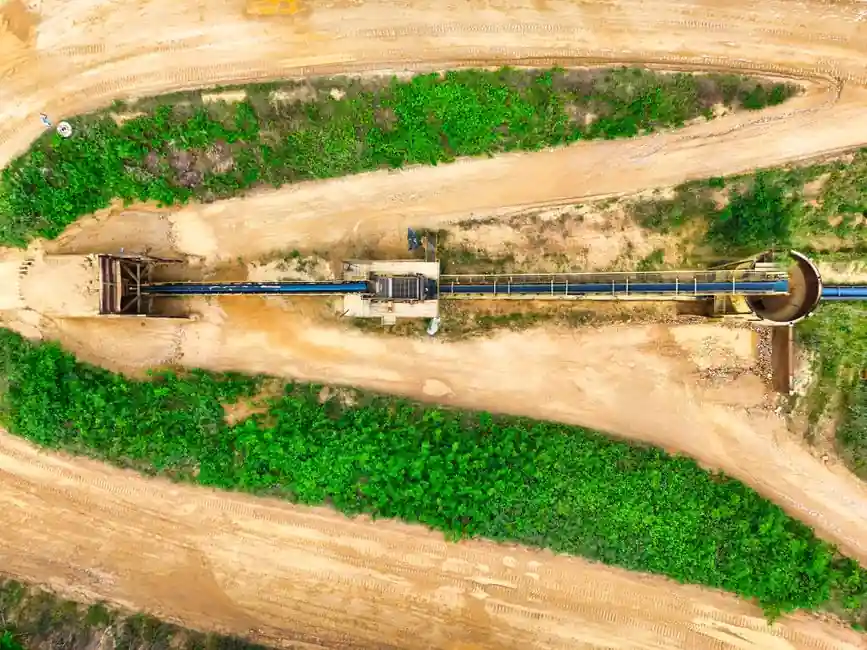
A long-center conveyor drive needs a tensioner sized for belt tension and shaft load, not simply for the visible span between pulleys [S1][S2].
This guide covers V-belt conveyor drives with long center distances, including spring idlers, gravity idlers, and fixed-center alternatives, with selection limits based on drive power, speed, torque, load, operating cycles, and mounting space [S2][S3].
Define the Drive Duty Before Choosing a Tensioner
Record motor power, driver and driven speeds, center distance, pulley diameters, belt section, starting conditions, load profile, operating hours, and reversal status before selecting a tensioner. These variables determine belt tension, shaft load, belt length, and the required tensioner force [S2][S3].
For a V-belt drive, a common design sequence starts with nameplate power and speed, then applies a service factor to obtain design power.
Long center distance affects the operating geometry and can produce high calculated belt tension with a shorter useful belt life. The Design Guide on Pulleys and Belt Drives states that long pulley-to-pulley distances yield high power ratings but shorter belt life, so the tensioner must solve belt-length change without overloading the shaft [S1].
A long drive also needs a defined operating envelope: industrial belt drives in the cited guide span from fractional horsepower to 7,000 hp or more, while modern belt drives can operate at efficiencies up to 95% or higher under suitable conditions [S1]. Do not use those broad ranges as a substitute for the actual drive calculation.
Choose Between Spring, Gravity, and Manual Tensioning
Spring-loaded idlers are normally the default for long-center belt drives because they remove slack automatically and reduce the risk of manual over-tensioning. A rotary tensioner uses a lever arm, while a linear tensioner mounts the idler or wear surface on a spring-loaded shaft [S3].
The main options differ in control, maintenance, and shaft consequences:
For the comparison, spring tensioning offers better automatic control than manual take-up, while gravity tensioning is simpler but less tolerant of shock loading. A belt tensioner should be selected for installed adjustment range, not for maximum belt pull.
Use a V-Belt Idler on the Slack Side

Place a belt tensioner against the slack side of the drive and inside the belt loop, with the idler positioned to provide nearly equal arcs of contact on the driver and driven pulleys [S3]. This layout maintains tension without reversing the normal bending direction of the belt.
A backside idler can increase wrap angle and power-transmission capacity, but it creates a reverse bend that reduces belt life [S3]. It can be justified when the calculated drive cannot meet the power requirement otherwise, but it should not be the default arrangement for a long conveyor span.
The tensioner idler should also be sized to avoid excessive bending stress. These figures apply to the belt section being selected, not to every idler material or profile.
Use a crowned pulley where tracking needs support, but do not treat crowning as a substitute for alignment. Correct alignment improves service life, while excessive misalignment causes improper tracking, uneven pulley wear, noise, and edge wear, with severity increasing with belt width [S4].
Do Not Use a Spring Tensioner in Every Drive
Spring-loaded tensioners should not be used in reversing drives. On reversal, the former slack side becomes the tight side, and the spring force may be insufficient to maintain proper tension [S3].
For a friction conveyor drive, the tensioning strategy must match the belt type rather than treating a V-belt idler and a synchronous-belt idler as interchangeable.
A tensioner is not an emergency brake or an independent stopping device.
For fixed-center conveyors, a floating shaft or an idler mounted in the take-up frame may be more practical than an external spring arm. The design must still provide controlled belt tension while preserving adequate bearing span and guarding. The selection logic for a fixed-center drive tensioner applies when the belt length cannot be taken up with a conventional spring arm.
Control Shaft Load and Tensioner Arm Overhang
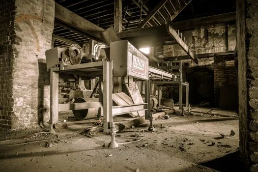
Keep the distance from the tensioner idler centerline to the face of the tensioner arm within the manufacturer's recommendation. Excessive overhang increases idler bolt load, tensioner-arm bending, and support-bushing load [S3].
Calculate the force carried by the arm from the calculated belt tension and the idler geometry. These are design aids, not substitutes for checking the actual conveyor loading and guard geometry.
Long center distance makes the idler location consequential because belt tension acts along two spans and creates a net radial load on the drive shaft. A tensioner that maintains adequate belt pull can also add a bending moment to the shaft, bearing, and frame. If the calculated idler load is high, move the idler closer to the supported frame or change to a take-up arrangement that reduces arm overhang.
For shaft support, compare the calculated belt load with the ratings of the existing bearings and any shaft-mounted components. A practical review includes the shaft collar, shaft coupling, and shaft key because any tensioner-induced reaction must pass through the same shaft system.
Check Belt Type, Material, and Wear Compatibility
Match the idler surface to the belt construction and operating environment. The flat-belt and V-belt families differ in friction behavior, groove engagement, and allowable drive geometry, while ribbed-belt and timing-belt drives use different engagement and tensioning requirements [S1][S3].
For long conveyor drives, use a crowned steel idler only after checking belt width, speed, duty, and contamination conditions. Do not substitute a flat idler for a grooved V-belt pulley or use a synchronous-belt profile on a friction drive. The idler must support the belt without edge cutting, and its contact width must match the belt section.
Industrial belts are generally non-serviceable and remain vulnerable to wear, oil, and debris contamination [S1]. A stainless idler does not eliminate belt wear, and a composite idler does not remove the need to check load and speed. For a separate material comparison, steel versus composite tensioner pulleys addresses wear-surface selection.
Specify, Test, and Maintain the Selected Tensioner
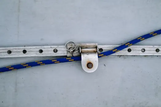
Specify the tensioner with belt section, minimum pulley diameter, idler width, permissible speed, arm travel, spring range, rated idler load, and mounting dimensions. The selection should also state whether the unit is for continuous, reversing, shock-loaded, or intermittent service, because those conditions change the required force and fatigue allowance [S2][S3].
At commissioning, verify pulley alignment, belt tracking, idler clearance, spring setting, guard clearance, and shaft runout. A backside idler reduces belt life, while an unsupported or overhung idler increases fastener, arm, and bushing loads [S3]. The belt-conveyor layout should provide access for inspection without exposing personnel to moving belt, pulleys, or tensioner hardware.
Set the baseline from the calculated drive, then inspect the drive after the commissioning run and at the specified maintenance interval. For a long-center conveyor drive, record belt tension adjustment, idler wear, bearing temperature, and tracking condition. Replace or correct the belt section, pulley diameter, alignment, or operating load if repeated adjustment is needed, rather than tightening the spring indefinitely.
Shortlist the tensioner only after confirming that it controls the expected belt elongation, fits the available mounting space, limits arm overhang, carries the calculated idler load, and matches the belt type. For reversing duty, exclude the conventional spring tensioner and redesign the tensioning arrangement [S3].