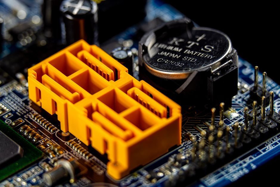
A battery management system (BMS) is the contract between upstream cell/pack hardware and downstream pack integrators, exposing SOC/SOH estimators, cell balancers, contactor management and protection logic as defined interfaces [S1]. On 2026-07-14 the working model treats BMS as four blocks — controllers, estimators, monitors, balancers — with libraries compatible to the `buildBattery` custom model output [S2].
Upstream feeds are cell datasheets, equivalent-circuit or single-particle parameters and thermal-runaway ARC test data; downstream consumers are BESS plant controllers, EV powertrain ECUs and DC fast-charge stations that pull state and limits in real time [S1][S2]. A 2026 reference peak-shaving example implements BESS + BMS under IEEE Std 1547-2018 and IEEE 2030.2.1-2019, treating BMS as a leaf under the energy-management system [S2].
BMS Functional Block Set vs Upstream Cell Data
Simscape Battery ships five BMS sub-libraries: Cell Balancing, Current Management, Estimators (SOC, terminal resistance, SOH, performance), Protection and Cyclers, all parameterised from manufacturer cell datasheets and HPPC test traces [S1][S2]. SOC estimators include a Kalman-filter implementation that converges from an inaccurate initial condition under noisy measurements, with the example marked Since R2024b [S2]. The Coulomb-counting method is provided alongside Kalman for comparison on the same plant model [S2].
Upstream cell data drives model resolution: Simulink lets the engineer trade fidelity versus simulation speed, parameterise cells from datasheets, model cooling plates with custom fluid paths and quantify cell-to-cell temperature variation as a cooling-efficiency metric [S1]. Fault injection is treated as a first-class input — examples cover ARC thermal-runaway characterisation and grouped parameter estimation for the single-particle electrochemical model [S1].
Downstream Interfaces: Contactor Logic, Pre-charge and Fault Tree
The Stateflow reference splits the BMS into two halves: a BMS Algorithms subsystem (Power System Control + Battery Management) and a Plant Model that holds the physical pack, contactors and pre-charge circuit [S3]. The Contactor_Management chart starts in two parallel fail-safe states (`OpenChargerContacts`, `OpenInverterContacts`), then closes a pre-charge circuit that equalises battery and load voltage through a capacitor before the main contactor closes — if the voltages are not equal within a defined window, the controller throws a fault [S3].
Fault detection runs four parallel monitors: contactor, overcurrent, cell temperature and cell voltage, with each branch using linked atomic subcharts and a `QualTime` maturation timer to suppress nuisance trips [S3]. Sensor-fault detection compares measured pack voltage against the sum of individual cell voltages, a standard pack-level consistency check used to catch voltage-sensor drift before it propagates into SOC error [S3]. For a stacked pack, the same SOC estimator and contactor logic feeds downstream into the inverter, DC fast charger or BESS plant controller without duplication.
Standards Boundary: Where BMS Stops and EMS Starts
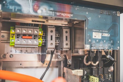
BMS internal state estimation and protection live below the plant-controller line; grid-tied BESS examples apply IEEE Std 1547-2018 for interconnection and IEEE 2030.2.1-2019 for energy-storage interconnection, with the BMS subordinated to the BESS controller for peak-shaving dispatch [S2]. The separation matters for spec writing: anything time-domain at the cell or module (cell balancing, contactor sequencing, fault maturation) is BMS; anything that bids power into a market or schedules a dispatch interval is EMS.
Thermal-runaway characterisation uses Accelerating Rate Calorimetry (ARC) test data, and HPPC pulse data is used to estimate equivalent-circuit parameters — both inputs come from the cell supplier's test report, not from a generic library value [S1]. For a single-particle electrochemical model, grouped parameter estimation is provided as a workflow when cell-level cycling data is available [S1].
Selection Map: Which BMS Architecture Fits the Pack
Three architectures dominate the 2026 brief: (a) distributed cell-monitoring ICs with a central pack controller, used in mainstream EV packs where per-cell voltage telemetry and passive balancing dominate; (b) master-slave modules in large BESS racks where the BMS talks to a PCS-level EMS and dispatches under IEEE 1547-2018; (c) integrated BMS-in-pack designs in ESS containers where the BMS and EMS share a single controller [S2].
Against four decision criteria the three split cleanly: (1) per-cell telemetry resolution — distributed ICs win at high cell count; (2) balancing current — active balancers sized by Simulink resistor-balancing blocks fit modular BESS; (3) grid-code compliance — master-slave BESS with an IEEE 1547-2018 wrapper is the only option for utility-tied storage; (4) development velocity — a model-based Simscape Battery + Stateflow flow with code generation compresses the BMS-software path against hand-coded C [S1][S2][S3].
Toolchain Discipline: From Plant Model to Deployment
MathWorks documents a four-stage flow — Create Battery Models, Develop BMS Algorithms, Test and Verify, Generate and Deploy — and quotes Romeo Power's Cecilia Wang on the speed/cost case: "Assessing battery pack performance using hardware prototypes can be both slow and costly, so we rely on simulation to ensure that we minimize hardware testing. Modeling and simulation with MATLAB, Simulink, and Simscape is faster, safer, and less costly than building physical prototypes" [S1]. Test and Verify covers battery-system fault simulation (30:23 video) and cell thermal-runaway ARC tests as gates before hardware-in-the-loop [S1].
Deployment targets the Simscape Battery "Deployment and Hardware-in-the-Loop Simulation" workflow, with estimators, balancers and protection blocks codegen-compatible with the custom `buildBattery` pack model — meaning the same plant model used in MIL/SIL transitions to HIL without a re-implementation [S2]. For the pack-level polyolefin separator supply risk discussion, the same Simscape cooling-plate and cell-to-cell temperature spread workflow lets the engineer quantify thermal margin before committing to a separator grade.
Failure Modes the BMS Must Catch
Overcharge, over-discharge, over-current, overtemperature and cell-voltage imbalance remain the canonical BMS protection set, with each fault implemented as a parallel Stateflow state that requires `QualTime` maturation before tripping [S3][S4]. Sogou Baike's functional list — accurate SOC estimation, dynamic monitoring of cell voltage/temperature/current during charge and discharge, and equalisation between series cells — maps directly onto the Simscape Estimators + Cell Balancing + Protection sub-libraries [S2][S4].
The hard constraints to spec: (1) the SOC estimator must remain stable under noisy current and voltage measurements — Kalman handles this where Coulomb counting drifts; (2) cell balancing must bring a series string within the SOC/SoH window the downstream EMS expects, or the BESS dispatch under IEEE 1547-2018 will derate; (3) contactor sequencing must include pre-charge equalisation, otherwise DC-link inrush welds the main contactor [S2][S3].
Sourcing Signals and Next Spec Gates
On the cell side, push for HPPC pulse data, ARC thermal-runaway traces and grouped single-particle parameter sets from the cell vendor before locking the BMS algorithm — the Simscape parameter-estimation blocks are tuned for exactly that data shape [S1]. On the system side, the IEEE 1547-2018 BESS reference and the IEEE 2030.2.1-2019 grid-storage standard are the documents to put on the spec sheet for any utility-tied project [S2].
Trackable next nodes: (1) the Since R2024b Kalman SOC example is the reference implementation to gate SIL convergence on; (2) the Stateflow `QualTime` maturation timer is the gate to copy into every contactor-fault branch on a new pack; (3) ARC and HPPC datasets from the cell supplier are the contractual gate to insert before BMS code is frozen [S1][S2][S3].
For component-level specifications, see asrs system, shuttle system, and sorting system.