
Carbon fiber placing-boom sections can extend a boom on the same chassis because a mature seven-section composite structure can reduce pump-truck boom weight by more than 40% [S7].
The gain is indirect rather than automatic: lighter sections allow additional length to be carried without overloading the chassis, but reach still depends on hydraulics, structural design, stability, outrigger setup, and operating limits [S1][S5].
What carbon fiber changes
Carbon fiber does not create unlimited reach on a fixed chassis. It lowers the mass penalty of each boom section, allowing a designer to add sections or extend the boom while preserving more of the chassis payload capacity [S1][S7].
Composite boom engineering also supports load-specific geometry. Rectangular hollow composite sections delivered a 25% weight reduction against comparable steel booms in one composite placing-boom application [S4].
The material is not simply substituted for carbon steel in a standard design. Joints, wall thickness, taper, local reinforcement, fatigue behavior, hose routing, and connection details determine whether a longer configuration is structurally practical. The boom is a moving, cyclically loaded structure, and added length also raises overturning demand as the boom extends [S1][S5].
How much longer the boom can be
A seven-section carbon-fiber boom has been reported to cut pump-truck boom weight by more than 40%, which creates room for extra boom length within a fixed chassis loading envelope [S7]. That percentage is a structural weight comparison, not a promise of 40% more reach, because reach depends on section geometry, joint design, and the folded dimensions of each section.
Published examples also show that separate placing-boom systems reach 28 m and 35 m while mounted on modular octagonal masts. The mounting arrangement permits free-standing heights of 70 ft with the 28 m boom and 50 ft with the 35 m boom without a counterweight [S2]. These figures demonstrate that reach is a system property involving the boom, mast, base, foundation, and installation method, not an isolated property of the boom tube [S2].
The decision boundary for a longer carbon-fiber configuration is therefore not simply “carbon versus steel,” but whether the complete vehicle remains within its rated gross vehicle weight, axle limits, boom load chart, outrigger reactions, and stability requirements.
Comparison criteria for boom options
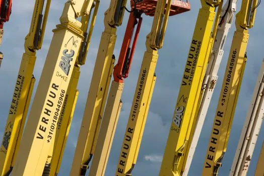
Carbon fiber, aluminum alloy, and alloy steel place-boom sections should be compared on the same four criteria. The first is section mass, because it consumes chassis payload; the second is stiffness and deflection under pumping load; the third is fatigue performance and joint durability; and the fourth is folded transport length. Only the first is clearly improved by carbon fiber in the available data. [S3]
A composite hollow section achieved a 25% weight reduction against comparable steel sections [S4]. The separate claim that a seven-section carbon-fiber structure reduces total pump-truck boom weight by more than 40% depends on the full assembly and cannot be transferred directly to every product [S7]. These figures show why a procurement comparison based on material name alone is inadequate.
Aluminum remains a credible lightweight option, while steel provides a different stiffness, weight, cost, and fabrication profile. The useful specification is not “carbon fiber is better,” but the measured reduction in boom mass, the allowable boom-tip load across the selected radius, the fatigue-life evidence, the vehicle weight added, and the resulting increase in horizontal or vertical reach. A carbon boom that saves mass but requires a larger chassis or more outrigger capacity may not solve the intended site constraint.
Where the longer boom creates value
A longer carbon-fiber boom is most useful when the operating envelope is limited by boom mass rather than by the building, mast height, pump output, or site footprint. A 28 m separate placing boom can be supported by a 70 ft free-standing octagonal mast, while a 35 m boom can be paired with a 50 ft mast configuration [S2]. This arrangement separates vehicle reach from building height and can suit projects where a long truck-mounted boom is difficult to maneuver.
For high-rise work, SANY says that free-standing height enhances flexibility and productivity, especially in high-rise buildings and large shopping centers, while its placing booms also feature full 360-degree rotation. A composite section may make a longer folded assembly more manageable for the chassis, but the assembly must still fit transport length, axle loading, route clearances, and deployment space.
The Z-fold versus roll-and-fold placing boom comparison matters because section count and fold geometry determine whether added carbon-fiber length can be packaged efficiently. Longer sections can reduce the number of joints, but they may also increase vehicle length and deployment clearance. A useful design review should compare both unfolded reach and folded transport geometry.
Chassis and site constraints remain decisive
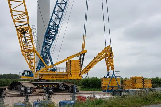
The same chassis cannot accept unlimited additional boom mass or length. Vehicle gross weight, axle ratings, outrigger span, foundation capacity, mast configuration, and the boom load chart control whether the extra sections are admissible. A separate-boom installation can be moved among several masts with a four-pin mounting system, but that modularity transfers the boom between structures rather than removing the stability checks at each destination [S2].
Longer reach also changes the stability envelope. As the boom rotates and extends, the overturning moment changes with boom length, outreach, load, counterweight, and support geometry. Added carbon-fiber sections must therefore be validated as a complete load case rather than accepted because the individual tube weighs less. SANY’s described validation process includes assembly and stability testing, component-level boom-system fatigue testing, and finite-element analysis [S5].
Placing booms are for placing concrete, not lifting. A safety bulletin states that concrete pump placing booms do not comply with crane requirements because crane compliance would require limiting the lifted weight at every possible boom configuration [S8]. Operators must not treat the reduced weight of carbon-fiber sections as permission to pick up loads or use the boom as a crane.
Specification and sourcing checks
Specify the configuration by vertical reach, horizontal reach, section count, overall folded length, total boom mass, tip-load limits across the load chart, connection type, chassis model, gross vehicle weight, and outrigger geometry. Merely stating “carbon fiber” does not establish equivalent performance between suppliers. CIFA’s own example shows that section thickness and dimensions vary within a section, making a material-only comparison unreliable [S1].
Separate placing-boom masts are available in modular 4 m and 6 m octagonal sections bolted together, with floor openings measuring 41-1/8 in by 41-1/8 in for clamp-style floor frames [S2]. Those installation dimensions belong to the described mounting system and should not be generalized to every mast. A carbon-fiber boom length is viable only when its joints, folding sequence, mast interface, foundation, and transport arrangement remain compatible.
The strongest procurement case is a documented reduction in mass without a corresponding reduction in allowable load, fatigue life, or reach. The 25% composite-section reduction versus comparable steel [S4] and more than 40% seven-section carbon-boom mass reduction [S7] are useful benchmarks, but they are not universal acceptance criteria. Request model-specific calculations and operating limits for the proposed longer boom on the exact chassis.
Track two signals before approving a longer configuration: the completed vehicle weight and axle utilization with all specified sections, and the published boom load chart for the maximum proposed reach. Both must remain within the selected chassis and support system, with no use of the placing boom for lifting [S8].