Rail foundries pour iron castings for engine blocks, rail car axles, suspension housings, coupling systems, and brake assemblies, and every pour sequence starts with a casting ladle matched to the part's mass and metallurgical requirement [S2][S5].
Hand-shank ladles cap out near 20 kg, geared crane ladles cover serial production, and steelmill transfer or treatment ladles run up to 300 tonnes (295 long tons; 331 short tons), a capacity envelope a rail foundry uses as its first sizing filter [S4].
Ladle Categories and the Capacity Bands That Drive Selection
Foundry ladles are rated by working capacity rather than physical size, which is why a 55-ton holding heat is a common serial-production benchmark for iron pours feeding rail-component lines [S1][S4]. Hand-shank vessels with a long handle keep the heat away from the operator and are limited to what one worker can safely carry; once a pour exceeds that, the foundry steps up to a geared crane ladle with a lifting bail and a manual or powered gearbox for rotation [S4].
For very large volumes, ladles run on wheels, sit on a ladle transfer car, or are slung from an overhead crane, and a second overhead lifting device provides the tilt, a configuration rail-component plants running high-tonnage ductile iron typically adopt for axle and brake-housing pours [S4]. Three functional prefixes matter for rail work: casting ladle (pour into moulds), transfer ladle (move metal from primary furnace to holding or auto-pour unit), and treatment ladle (convert cast iron to ductile iron by alloy addition in-ladle) [S4].
Spout Geometry and Pour Control for Rail Moulds
Spout style controls how molten metal enters the mould, and rail foundries typically choose from lip-pour, bottom-tap, or outside teapot spouts built into a welded or riveted steel shell, with a covered or open top per the pouring system's needs [S1]. Teapot and bottom-tap designs give cleaner, more laminar metal entry than a simple lip pour, which matters for thin-wall brake housings and suspension brackets where oxide entrainment causes inclusions and scrap [S1][S3].
The most common ladle shell is a vertical cone, a shape that adds strength and rigidity, while internal refractory lining, either pre-cast firebrick or refractory concrete, isolates the steel shell from molten iron at typical pour temperatures [S4]. Refractory concretes have largely superseded pre-cast firebricks in many countries because monolithic linings reduce joint-related wear during repeated 55-ton holding cycles [S1][S4].
Mechanical Drive Train: Worm, Gear, and Bearing Package

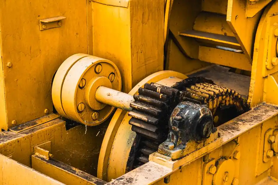
Foundry ladles are powered by a worm-and-gear tilting mechanism that the operator uses to rotate the vessel and pour, and these components take the worst of the heat and load [S1]. Worms and gears on heavy ladles are commonly cut from case-hardened steel or alloy steel to balance wear resistance and core toughness, because the same shaft sees thermal cycling on every pour [S1].
Bearings and bushings carry the full ladle weight and let the vessel rotate, so high-strength plain or anti-friction bearings sized for the rated capacity are the standard fit on Whiting-style foundry ladles used for iron pours [S1]. Gaskets, oil seals, and plungers seal the lid, body, and hydraulic system, and they are routinely specified in heat-resistant rubber or high-strength steel so the seal package survives the same thermal cycles as the lining [S1].
Matching Ladle Type to Rail-Component Geometry and Iron Grade
Rail-component foundries commonly pour ductile iron, high-strength ductile iron, and austempered ductile iron (ADI) into engine, axle, suspension, coupling, and brake parts, and that grade mix sets the ladle strategy [S5][S6]. Ductile and ADI grades are produced via in-ladle magnesium treatment, so a treatment ladle (or a transfer ladle feeding an auto-pour unit) is the right hardware for that step, not a simple casting ladle [S4][S6].
Thin-wall, high-tolerance parts such as brake housings and bearing adapters are best fed by bottom-tap or teapot ladles that deliver low-turbulence metal; heavier axle and engine castings tolerate lip-pour crane ladles at higher pour rates [S1][S2][S7]. When the production mix is dominated by short-run or prototype work, smaller hand-shank or small geared ladles are the economic fit, since the per-pour refractory and energy overhead of a 55-ton vessel only amortizes on long serial runs [S1][S4].
Comparison: Ladle Types Against Four Rail-Foundry Decision Criteria
Hand-shank ladles, geared crane ladles, and transfer or treatment ladles line up differently against capacity, metallurgical flexibility, spout control, and capital cost, which is the practical decision grid a rail foundry walks through during casting tooling planning [S1][S4]. Hand-shank vessels cap near 20 kg, only support casting-ladle duty, and offer basic lip-pour control at the lowest cost; geared crane ladles scale to multi-ton pours, accept any spout style, and add a powered rotation gearbox; transfer and treatment ladles scale into the hundreds of tonnes, enable in-ladle alloying for ductile iron and ADI, and require the heaviest refractory and drive investment [S1][S4][S5].
For rail-component lines, the practical rule of thumb is to match the ladle's working capacity to the heaviest single cast in the production mix, select spout geometry by the thinnest-wall part on the floor, and only adopt a treatment ladle when the iron grade requires in-ladle magnesium or similar alloy chemistry [S4][S5][S6].
Integration With Moulds, Tooling, and Downstream Finishing
A ladle is only as useful as the casting mould and die-casting workflow it feeds, and a rail-component line typically pairs the chosen ladle with green-sand, shell-mould, or airset moulds, plus cores for internal passages [S2][S3][S7]. Eagle Alloy's railroad portfolio includes coupler components, brake housings, bearing adapters, and brackets produced via shell molding and airset casting, a process map that lines up directly with the geared crane ladle class [S2].
Downstream, value-added services such as machining, heat treatment, and paint are routinely co-located with the casting cell, so a rail foundry's ladle selection indirectly fixes the throughput the rest of the finishing line must support [S5]. Engineers using advanced iron and sand flow simulation before tooling cut, a step Waupaca Foundry highlights for rail programs, rely on a stable ladle pour signature to make the simulation results meaningful, reinforcing the case for a dedicated ladle per part family rather than a one-ladle-fits-all approach [S5].
Limitations, Failure Modes, and Sourcing Constraints
Foundry ladles are a wear part: refractory lining life, worm-and-gear wear, and seal degradation all dictate scheduled rebuild intervals, and the original-equipment drawings that Whiting holds for worms, gears, bearings, and gaskets are what keep replacement parts within thermal and load spec [S1]. Sourcing constraints to flag in 2026 include long lead times on case-hardened steel worms and on monolithic refractory concrete installation crews, both of which can stall a rail-component cell if not pre-staged [S1][S4].
Ladle selection also has to respect the iron grade's chemistry window: a treatment ladle sized for ductile iron magnesium addition is not interchangeable with a transfer ladle on a ductile-to-ADI transition, since ADI requires tighter temperature and alloy control through the pour [S4][S5][S6]. For a deeper look at how the moulding side of the line is matched to similar rail-component geometries, see the gravity die casting spec map for rail work, which lines up with the geared crane ladle class covered here.
Background reading: Perimeter alarm selection for laboratories: PIDS types, indoor pairing, and spec map.