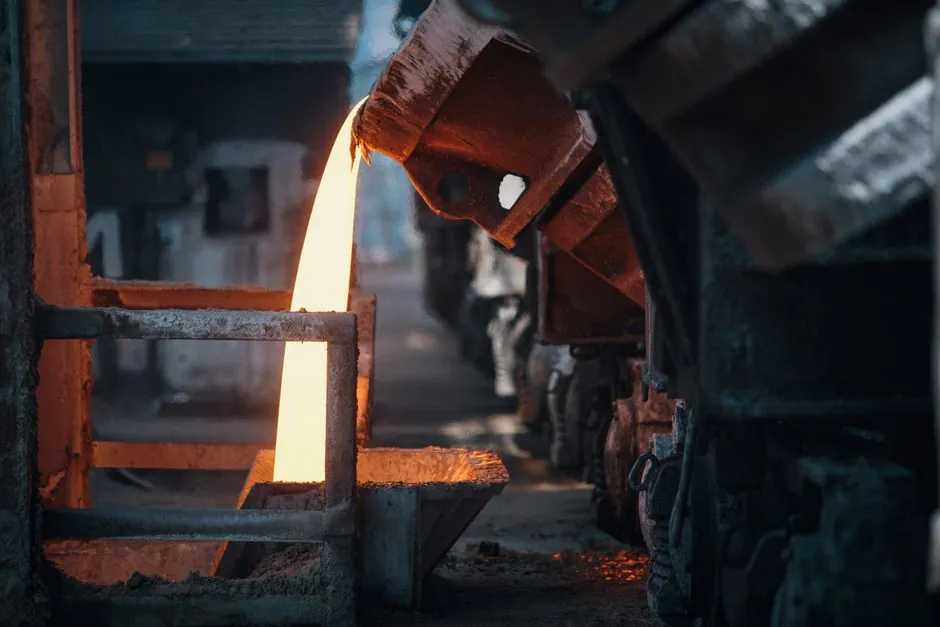
Inductor-loop plugging in a channel induction furnace originates from iron oxide reacting with bath oxygen to form spinel clusters that nucleate on the cold refractory of the inductor throat, then grow as a low-melting silicate/sulfide ceramic that progressively chokes the molten metal loop [S3].
Because the channel inductor operates as a narrow, refractory-encased loop of liquid metal that transfers both the melt and the secondary current of the induction furnace, any restriction directly reduces electrical efficiency, raises bath superheat demand, and can freeze the loop entirely, forcing a controlled remelt under tight thermal limits [S1][S4].
Root Cause: Iron Oxide Spinel Clusters, Not "Dirt" Alone
Molten iron oxidation produces iron oxide that decomposes inside the bath and continuously releases free oxygen atoms, which then react with other oxide species to build iron-oxide-based spinel clusters [S3]. These clusters act as a glue combining Mg, Si, Al, Mn, and Ca oxides into dense, high-melting agglomerates that do not dissolve in the iron bath and preferentially deposit on the coldest refractory surface they encounter, the inductor channel wall [S3].
Once a thin solid film of slag forms on the channel wall, subsequent buildup proceeds faster because the deposited layer is crystallographically similar to the liquid slag attempting to precipitate, so nucleation sites are already in place; this is why operators describe channel clogging as a self-accelerating, classical nucleation-and-growth phenomenon [S1][S2].
Why the Inductor Channel Is the Weak Point
Unlike the open bath of a melting furnace or a holding furnace, the inductor channel is a narrow refractory-encased throat where wall temperature runs below the local bath temperature; the temperature gradient is precisely what freezes the first slag film onto the surface and anchors the deposit [S1][S2].
Channel cross-sections are typically small relative to the upper case, so even a 2-3 mm reduction in effective bore measurably increases flow restriction; foundry case data show a 3-ton coreless furnace losing 20% of its working volume to analogous sidewall buildup, and the inductor channel responds on a smaller geometric scale with a much steeper efficiency penalty [S5]. Buildup in this critical loop must be held to a minimum because, if the loop is allowed to freeze, remelting it risks rupturing the channel and breaking the molten metal circuit [S2].
Where the Oxides Come From: Charge, Atmosphere, Treatment

Foundry data identifies five primary oxide/sulfide sources: oxidation of the molten metal surface; dirty, rusty, or sand-encrusted scrap charge; erosion of upstream refractories in the upper case or receiver; contamination from inoculation and nodulizing additions; and by-products of desulfurization treatments, including sulfide pickup from machining fluids and dirt on returns [S2].
Buying cheaper, less-clean scrap directly trades raw-material cost for higher slag load, slower melt rates, and increased inductor-loop risk, an economic trade-off that often shows up first as rising kWh/ton before the channel actually plugs [S2][S5]. Sulfide contribution is frequently under-appreciated: insoluble sulfides ride the same nucleation pathway as oxides and contribute to low-melting silicate deposits on the inductor wall [S1][S2].
Prevention Options Compared Against Four Decision Criteria
Operators have four practical levers; each scores differently on root-cause removal, refractory life impact, operator safety, and capital cost. [S5]
Iron deoxidation chemistry (e.g., deoxidizer additions to eliminate free bath oxygen) targets the root cause by preventing spinel formation in the first place, preserves refractory, removes manual-entry risk, and adds consumable cost per heat [S3].
Sodium-based fluxing (e.g., Redux EF40-class fluxes) coagulates emulsified non-metallics, lowers slag melting point, and lifts slag off the wall so it can be deslagged, preserving refractory and giving moderate cost, but does not by itself eliminate iron oxide generation [S1][S5][S6].
High-temperature bath "run-ups" to remelt spinel deposits are a common but counter-productive response that significantly shortens furnace and inductor service life while leaving the oxide-generation mechanism untouched [S3].
Mechanical rodding of the inductor channel physically clears the bore but is widely flagged as a man-killer procedure that should be avoided where chemical alternatives are available, and it can damage the channel refractory lining [S3].
Fluxing Chemistry: Why Sodium-Based, Not Fluorspar

Foundries historically avoided fluxing because fluorspar-based fluxes attack alumino-silicate refractories and shorten campaign life, but sodium-based fluxes developed over the past 20 years have demonstrated the ability to minimize and eliminate buildup in inductor throats and pressure pour furnace channels without measurable refractory damage [S5].
Flux performance is governed by the same physics as the problem: fluxes lower the viscosity and melting point of the emulsified slag so it floats out of the bath before it can wet the cold channel wall, and they reduce the contact time during which a stable nucleating film could form [S1][S5][S6]. Routine, frequent small additions are more effective than infrequent large doses because they prevent the initial solid film from anchoring, which is the rate-limiting step in the buildup mechanism [S1][S5].
Process Signals That the Channel Is Beginning to Clog
Three measurable shifts warn the operator before the channel freezes: rising specific energy consumption (kWh/ton) at constant bath temperature, longer time to reach pouring temperature from a given holding setpoint, and higher secondary voltage / current imbalance on the inductor power supply as the molten metal loop's effective cross-section shrinks [S1][S4].
Patent and field data on the related failure mode describe the clog as a flow restriction in the molten metal circuit that directly degrades the electrical efficiency of the inductor, confirming that the first symptoms are electrical, not mechanical [S4]. Operators who track these three trends on a per-shift basis catch incipient plugging while the slag is still emulsified, and at that point a sodium-based fluxing routine can clear the bath without thermal or mechanical intervention [S1][S5].
Operating Discipline That Keeps the Loop Open
Consistent practice across documented foundry operations comes down to four habits: specify clean, low-rust charge and dry returns before they enter the crucible furnace or channel upper case, apply small frequent sodium-based flux doses rather than large periodic doses, monitor kWh/ton and inductor secondary electrical values per shift as leading indicators, and avoid both high-temperature run-ups and mechanical rodding of the inductor loop whenever chemistry-based prevention is available [S1][S3][S5].
Trackable signals to watch over the next reporting cycle: (1) kWh/ton drift above the established baseline at constant pour temperature, indicating onset of restricted loop cross-section; (2) rising frequency of deslagging cycles per shift, indicating that emulsified oxide load has increased; (3) any change in inoculant or desulfurizer supplier, since minor-element chemistry shifts alter the spinel population feeding the channel [S2][S3][S4].
Related analysis: Why FRP Costs More per Tonne Than Steel Despite Weighing a Quarter as Much.