The sintering point of a molding sand is the temperature at which the aggregate begins to soften and fuse, well below its full melting point, and it is this lower edge of the fusion range that decides whether a mold burns onto a casting [S2]. Refractoriness, defined as the sand's ability to withstand molten metal without degrading, is therefore tied to the sintering onset, not to the headline cone-fusion temperature that most data sheets publish [S4].
For practical foundry work, that distinction matters because burn-on, metal penetration, and veining all originate in the 1000 °C to 1500 °C window where the binder and the finest sand fractions start to sinter long before the bulk grain liquefies. Choosing a sand whose sintering onset sits above the pouring temperature of the alloy is the single most direct way to control those surface defects [S2][S3].
How the Sintering Test Actually Works
The Bureau of Standards Letter Circular 248 procedure, published 24 April 1928 and still cited in foundry QA practice, builds a 2 in × 2 in × 1 in rammed specimen, dries it at 105–110 °C for at least one hour, then presses a platinum ribbon heater against the rounded face under its own weight [S2]. A carbon-plate resistance (about 1000 W, 0.04–4 Ω, 18 in × 6.25 in × 7 in) ramps the ribbon while an optical pyrometer reads the brightness temperature, with an emissivity correction table converting observed values to true temperature from 1000 °C to 1500 °C in 25 °C steps [S2].
The reading taken at the moment the sand first sticks to the ribbon and refuses to fall away is logged as the sintering point; that value, not the higher fusion point, is the property that the foundry actually needs to know, because it marks where burn-on starts [S2]. Above about 1320 °C true temperature the procedure switches from a clear pyrometer sight to an absorbing glass, so labs running the original method need a matched optical setup to stay within the calibrated range [S2].
Why Sintering Point Beats Melting Point for Refractoriness
Full fusion of a silica grain sits well above 1700 °C, but iron and steel pouring temperatures sit at 1300–1550 °C, bronze and brass at 950–1200 °C, and aluminum at 660–780 °C, so the alloy never reaches the headline melting point at all. The failure mode is governed by what happens to the binder bridges, the clay coatings, and the finest grain fraction first, which is exactly the lower end of the fusion range that the sintering test captures [S2][S3].
For ferrous work, aggregates with sintering onsets at or above 1500 °C such as chromite, zircon, and high-purity ceramic sands (e.g., SphereOx) are typically selected, while silica-based green sand systems are usually kept below 1300 °C metal contact or used with backing sand that never sees the molten front [S3]. Specialty aggregate data sheets explicitly list thermal expansion, heat transfer, refractoriness, and molten-metal penetration resistance as the four levers that separate silica from the higher-temperature families, and refractoriness on those sheets is reported as a sintering or softening onset, not a true melting point [S3].
Comparing Aggregate Families Against the Sintering Criterion
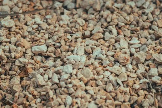
Silica sand (mostly SiO2) is the most widely used foundry aggregate, but it is also the first to sinter, so it pairs naturally with green sand, chemically bonded molds, and nonferrous alloys where the metal front stays under about 1200 °C [S3][S4]. Chromite sand offers high thermal conductivity and a chilling effect that suits steel, iron, and other high-temperature jobs that need penetration resistance, while zircon sand contributes low thermal expansion and resistance to wetting by molten metal, which preserves dimensional stability on the mold face [S3].
Olivine is positioned for nonferrous and manganese-steel applications, with thermal properties and non-wetting behaviour that suit selected facing-sand work, and ceramic alternatives such as Biasill staurolite, Zircore, Kyasill, and SphereOx are listed for foundries evaluating aggregates outside the silica-chromite-zircon core trio [S3]. A 2025 review of sand-property effects on part quality confirms the trade-off the sintering point enforces: coarser grains improve permeability and gas escape but yield rougher surfaces and lower mold strength, so a refractoriness-driven aggregate choice has to be balanced against grain fineness for finish and venting [S6].
What Burn-On and Penetration Cost You at the Sintering Edge
Once the aggregate approaches its sintering onset, molten metal starts to wet the pore network and metal penetrates the inter-grain gaps, producing burn-in, veining, and a fused sand layer that is hard to clean off the casting [S2]. Foundries counter this in two ways: by selecting a higher-onset aggregate for the facing sand, and by controlling the sintering behaviour of the backing sand through binder choice, moisture, and additives such as coal, pitch, sea coal, and silica flour that shift when the surface layer pyrolyses and seals [S4].
The same 2025 review notes that fine-grain, high-bonding systems give smoother castings and stronger molds at the cost of permeability, so the sintering point is really a process-wide constraint, not a single-number spec: the aggregate, the binder, the moisture, and the grain-size distribution together determine where on the temperature ramp the mold face will fail [S6]. For 3D-printed sand molds, a 2024 study on hollow multi-layer shell structures showed that geometry, not just aggregate, shifts the failure mode from penetrative cracking to local breakage, because the shell layout changes how heat leaves the casting and how the sintered layer accumulates [S1].
How Sand Molds Fail Beyond Refractoriness
Refractoriness is one of seven properties a molding sand has to deliver, alongside collapsibility, cohesiveness, adhesiveness, plasticity, permeability, dry strength, and green strength, and over-specifying refractoriness at the cost of collapsibility causes hot tearing and cracking in the casting as it cools [S4]. Sand molds are also inherently fragile, limited to low filling speeds and pressures, and are poor heat conductors, which is why facing sand carries the thermal load and backing sand handles everything else [S7].
That division is why foundries using automated systems lean on reconstituted system sand for the bulk of the mold and reserve higher-sintering aggregates for the face: the backing volume never sees the metal front, so a lower-cost, lower-refractoriness sand can be reused indefinitely, while the thin face layer is the only material that actually has to survive the sintering window [S4]. The Bureau of Standards test is run on the heap, floor, or car sample that faces the metal, not on the bulk backing inventory, because the sintering point is a facing-sand property in practice even though the procedure is identical [S2].
Field Signal: Sintering Point Becomes a Design Input in 3D-Printed Molds
Tool-free 3D sand printing, as commercialised on ExOne and voxeljet binder-jetting systems, lets foundries change aggregate, binder loading, and shell geometry on the same CAD file, and case data from 2025–2026 shows production prints up to 7.5 m, single-piece impeller cores that cut lead time by roughly half, and stack sizes of up to 480 cores per build with about 30% cost reduction on selected parts [S5]. The mechanical-property study on hollow multi-layer shells confirms that geometry changes the high-temperature residual tensile, compressive, and bending strength, which is the same temperature window the sintering test probes [S1].
For an engineer specifying aggregate, the practical signal is that the sintering point of the chosen sand, not its melting point, has to be cross-checked against the alloy pouring temperature, the binder chemistry, and the mold geometry, with coarse grains accepted where surface finish allows and finer, higher-sintering aggregates reserved for the face. Related process detail on binder behaviour and curing windows is covered in Warm Box vs Hot Box: Curing Temperature and Catalyst Logic, and the upstream furnace control that drives pouring-temperature stability is tracked in Cupola Shaft Charge Hanging and Bridging: Root Causes and Control.
For component-level specifications, see sand casting mold, casting mold, and mold base.