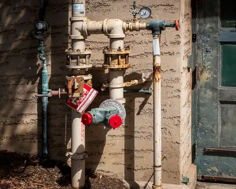
A pilot-operated check valve is an on/off device that excels at static load holding with near-zero leakage, while a counterbalance valve is a modulating motion-control valve that combines a reverse free-flow check with a pilot-operated relief to control descending or overrunning loads [S1][S2].
For a horizontal clamp, a tool-position lock, or any cylinder that must hold still under pump-off conditions, the pilot-operated check valve is the standard pick and typically costs 30-50% less than an equivalent counterbalance valve [S2]. For any vertical cylinder, crane boom, winch, or actuator that moves while gravity acts on it, the counterbalance valve is mandatory, because a pilot-operated check on a descending load causes the valve to snap open and shut, producing the ratcheting motion that damages rods, seals, and fittings [S1][S3].
Operating Principle: On/Off vs Modulating
A pilot-operated check valve, also called a pilot-to-open check, has two valid states: fully open or fully closed, and no in-between metering position [S1][S2]. The check element is held closed by a spring plus system pressure until a pilot signal on the opposite side overcomes the differential and cracks the poppet; once the pilot signal collapses, the valve re-seats immediately. Because the seat is metal-to-metal with a soft insert in most industrial designs, static leakage is typically under 1 drop per minute, which is the property engineers exploit for long-term position holding [S2].
A counterbalance valve is a pilot-operated relief stacked in parallel with a reverse free-flow check [S2][S8]. In the free-flow direction, oil passes through the check with minimal pressure drop, lifting the load. In the controlled (meter-out) direction, the relief element throttles flow, creating backpressure that decelerates the load. The valve is adjusted to a cracking pressure set roughly at 1.3x the maximum load-induced pressure at the actuator port, a ratio that gives enough margin for pressure spikes while still allowing pump pressure to open the valve and lower the load on command [S2].
Load-Holding Performance Numbers
Leakage and creep separate the two devices in real circuits. Pilot-operated check valves in good condition hold static loads at less than 1 drop per minute, so a 5,000-lb clamp stays put indefinitely with no measurable rod drift [S2]. Counterbalance valves leak more by design: spool-type elements pass 3 to 5 in³/min (roughly 50 to 80 mL/min) which produces noticeable actuator creep, while poppet-type counterbalance elements leak only 3 to 5 drops per minute, close to the pilot check range [S4].
Adjustment behaviour also diverges. An internally piloted counterbalance valve must be re-set every time the working load changes, because the cracking pressure reference is the load pressure itself, while an externally piloted counterbalance takes its pilot signal from a separate circuit, so the same valve setting works across a range of loads [S4]. A pilot-operated check valve has no pressure adjustment; either the pilot ratio (commonly 3:1 or 4:1) is built into the cartridge or it is not [S1].
Why Pilot Checks Ratchet on Descending Loads
The dangerous failure mode of a pilot-operated check on a vertical, gravity-loaded cylinder is well documented. As the load starts to fall, oil leaving the cap end flows through the check toward the pump. Pump flow cannot keep up, the pilot signal on the cap-end check collapses, and the check snaps shut [S1][S3]. Pump pressure then rebuilds, reopens the check, and the cycle repeats. The cylinder moves in jerky increments, each one a shock load on rod bearings, hose ends, and seals [S1][S3].
Three workarounds exist when a pilot check is already in the circuit. Adding a meter-out flow control between the cylinder and the check smooths the pilot signal by throttling flow on the cylinder side and preventing pump-side pilot pressure loss; this is the standard repair described in fluid power training material [S3]. Switching to a counterbalance valve eliminates the ratcheting entirely, because the relief element modulates continuously rather than snapping [S2][S4]. Using a dual counterbalance arrangement (one on each side of the cylinder) handles loads that go over-center on mobile booms, where the load reverses direction and tries to over-speed the pump [S1][S4].
Decision Matrix: When Each Valve Wins
Four decision criteria separate the two valves cleanly. On leakage, a pilot-operated check is the winner (under 1 drop/min vs 3-5 in³/min for spool counterbalance) [S2][S4]. On motion control under gravity, a counterbalance is the only acceptable option, because pilot checks cause ratcheting on descending loads [S1][S3]. On cost, a pilot-operated check is 30-50% cheaper than a comparable counterbalance, so specifying a counterbalance on a static clamp is wasted money [S2]. On adjustment effort, a pilot check is set-and-forget, while an internally piloted counterbalance must be re-set for each new load [S4]. For a broader look at how these two fit alongside other cartridge-style hydraulic valves, the cartridge vs subplate hydraulic valve spec decision map is a useful companion reference.
The selection rule is short: pilot-operated check for static holding and clamp locking; counterbalance for any actuator that moves while gravity is a factor. Mobile equipment designers apply this rule to crane booms, outriggers, aerial lift platforms, and forestry heads; industrial designers apply it to vertical presses, platen stops, and any cylinder oriented rod-down with a suspended mass [S1][S5].
Standards, Sizing, and System Integration
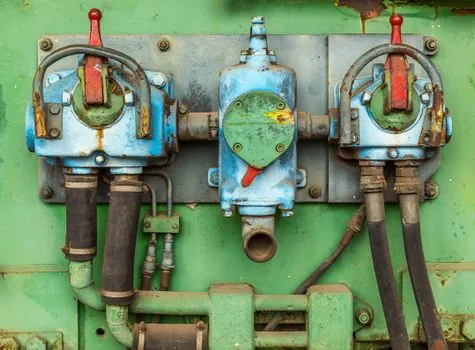
Counterbalance valves are commonly specified to NFPA T2.6.1 / ISO 4413 hydraulic fluid power safety guidelines, and are most often supplied as cartridge-type bodies in standard cavities (Cetop 3, Cetop 5, and Sun/Manifold common-cavity patterns are typical) so that a single block can be reconfigured as load changes [S1][S4]. The cracking pressure is set to approximately 1.3x the maximum load-induced pressure at the actuator port, a rule of thumb that keeps the valve closed during normal pump-pressure operation and opens it cleanly when the directional valve shifts to lower the load [S2].
Pilot-operated check valves are specified by pilot ratio (the ratio of pilot-area to poppet-area), with 3:1 the most common and 4:1 or higher used where lower pilot pressure is available; a higher pilot ratio reduces the pilot pressure required to open the check, which matters when the actuator is sized for low system pressure. For more context on the underlying check valve family and the hydraulic valve categories these devices belong to, the encyclopedia entries are worth a read. Related motion-control devices in the same architecture are the hydraulic actuator and the hydraulic cylinder that the valve protects, plus the swing check valve variant used on return-line applications.
Limitations and Failure Modes to Watch
Counterbalance valves do not lock a hydraulic motor at rest, because the motor itself has internal leakage paths; a braking valve or a mechanical park brake is required for static motor holding [S4]. Spool-type counterbalance valves leak enough to cause measurable cylinder creep over minutes, which is unacceptable on precision stop applications; poppet-type counterbalance elements or a pilot check in parallel are the standard remedy [S4].
Pilot-operated check valves fail open when the poppet seat is contaminated, and fail closed (lock the load in place) when the pilot signal is lost, which is a fail-safe mode that designers rely on for vertical lifts and suspended tooling [S1][S5]. A contaminated pilot check that fails partially open will let a load drift slowly, and the symptom is a cylinder that settles overnight rather than holding position, a common field complaint on older machine tools [S1].
Trackable signals to watch over the next procurement cycle: the broader push toward IO-Link and CAN-J1939 valve diagnostics, which is starting to appear on higher-end counterbalance cartridges, and the ongoing move toward poppet-only counterbalance designs as machine builders react to the creep liability of spool elements [S2][S4]. For safety-critical vertical lifts, dual counterbalance plus a mechanical lock remains the configuration most builders and end users specify.