
Inline metrology is the stronger defect-containment choice when a process can be corrected at the station that creates the error, because in-process inspection catches deviations at their origin before downstream operations add cost [S1].
End-of-line inspection remains necessary for final functional validation, first-article qualification, complex dimensional verification, and investigation of anomalies raised by inline systems [S4][S5].
Define the inspection scope before selecting equipment
Inline metrology measures dimensions, surface characteristics, composition, or defects while the product remains within the production flow [S2]. It can execute automated measurements without stopping production or removing samples, and its result can be used to alarm, stop the line, adjust machine parameters, or transmit data to a PLC or MES [S2].
End-of-line inspection evaluates a completed product against functional requirements. Typical checks include leak tests on sealed housings, electrical continuity checks on wiring harnesses, functional tests of assembled mechanisms, and final dimensional verification [S5]. In-process inspection catches defects at the point of origin, while end-of-line testing validates the finished product against functional requirements [S5].
In-process inspection is the narrowest containment scope in the comparison: a single station and part can be isolated when a deviation is found, rather than placing an entire batch at risk [S1]. At-line inspection occupies the middle ground because a sample is removed for checking at a dedicated station adjacent to production, while offline inspection takes the workpiece to a separate laboratory, CMM, optical system, or manual workbench [S4].
Compare the two approaches by measurable criteria
Inline metrology leads on detection latency, containment scope, root-cause traceability, and process-drift sensitivity, but its cycle-time burden and station cost can be disadvantages. End-of-line inspection supports deeper analysis and functional realism, with delayed detection and greater exposure to scrap and rework as the main penalties [S1][S5].
In-process inspection catches deviations at the station where they originate, before downstream operations add cost and bury the root cause [S1]. The named BIW application delivers in-line coverage of more than 500 features per station cycle, supporting a shift from sampling to 100% feature inspection [S1]. That ratio is specific to the cited application and should not be transferred without a line-specific trial.
Root-cause traceability also separates the methods. An inline result is tied to the station that generated the deviation, while an end-of-line pass or fail result may be ambiguous across many prior operations [S1].
End-of-line inspection has the advantage when the defect depends on assembled-state interaction. A seal may meet dimensional limits while the finished housing still leaks because of surface finish, gasket compression, housing distortion, or fastener-torque sequence [S5]. Inline metrology cannot replace that test unless the selected sensor actually reproduces the relevant service condition.
Match sensor choice to the defect physics
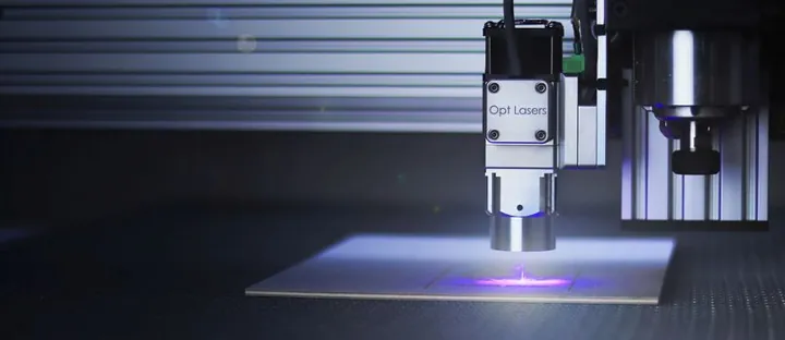
Inline metrology is not one technology. Available sensors include lasers, cameras, spectrometers, lidar, tactile probes, and thermal sensors; vision systems, laser or optical sensors, contact or non-contact gauges, 3D scanners, and spectroscopy each address different materials and accuracy requirements [S2].
Component orientation is a natural machine-vision application, force and displacement can be monitored during a press-fit, and a laser micrometer can measure a critical dimension immediately after machining [S5]. Inline surface inspection measures the workpiece surface without moving the workpiece outside the production line [S6]. In semiconductor production, in-line e-beam wafer metrology and defect inspection address measurement and inspection within the process route rather than confining all checks to a separate final gate [S3].
Offline equipment can provide more measurement axes, longer dwell time, and more complex fixturing than a production-mounted system because the workpiece is isolated [S4]. A CMM or laboratory optical system is therefore a rational choice for complex dimensions, first-article inspection, new-tooling verification, and root-cause analysis [S4]. For calibration and optical resolution, the arithmetic behind pixels per millimeter for inspection must be tied to the smallest feature that the production line is required to detect.
Use inline metrology for prevention and EOL for proof
Use inline metrology for component-placement errors, weld-duration drift, critical dimensions, surface defects, and other deviations that can be assigned to an upstream operation and corrected before additional value is added [S1][S5]. It is also the preferred route when every part must be screened, because inline inspection can provide 100% part coverage while production continues [S4].
Use end-of-line inspection for leak tightness, electrical continuity, assembled mechanism performance, service-condition simulation, and final acceptance criteria [S5]. Keep offline inspection for first-article qualification, complex dimensional verification, and detailed investigation after an inline anomaly is detected [S4]. At-line sampling remains useful for random spot checks and for confirming that an inline rejection represents a real defect before stopping production [S4].
A combined architecture is usually the stronger engineering choice. Place inline metrology at operations with clear feedback value, retain end-of-line functional testing as the release gate, and route exceptions to offline measurement. This arrangement shortens the defect-feedback loop without removing the final validation that a customer cares about [S1][S4][S5].
Budget the throughput and integration penalties

Each in-process inspection station adds equipment, calibration, maintenance, floor space, and a potential line-stop failure point [S5]. Inspection also consumes cycle time: a 0.5-second check at each of 12 stations adds 6 seconds to total throughput [S5]. The purchase price is therefore not the full economic comparison.
Inline systems also require an accuracy, repeatability, resolution, response-time, uptime, and total-cost-of-ownership review [S2]. Their controls may need to exchange quality decisions with PLCs, SCADA systems, MES, or ERP platforms through OPC UA, Ethernet/IP, Modbus, or MQTT [S2]. A sensor that cannot clear the takt time, maintain calibration, or trigger the correct downstream action does not create useful containment.
The cited BIW configuration reports sub-millimeter accuracy and confidence above 99.7%, while expanding from sampling toward 100% feature inspection [S1]. These figures are useful acceptance targets for a comparable trial, not generic performance claims for all inline metrology. The project-specific definition of confidence, characteristic coverage, false-accept rate, false-reject rate, and response time should be written into the acceptance test.
Define sourcing, calibration, and acceptance controls
For inline optical inspection, define the field of view, required spatial resolution, illumination method, camera response, calibration procedure, and detection threshold before comparing vendors. For dimensional systems, state the measurand, tolerance, environmental condition, sampling mode, and required repeatability. For functional EOL tests, specify the pressure, vacuum, electrical load, temperature, torque sequence, and pass criterion rather than using a generic station description [S5].
Digital traceability and consistent calibration support compliance workflows involving FDA, NIST, and ASTM requirements in the cited inline-measurement guide [S2]. These organizations and standards must be matched to the product, process, and jurisdiction. They do not replace a control plan, gauge repeatability and reproducibility study, or documented acceptance criteria.
The next engineering step is a three-line trial: verify one inline sensor at the source station, compare its findings with one offline reference method, and retain the EOL functional test as the independent release check. Track detection latency, defect coverage, false calls, missed defects, cycle-time consumption, calibration interval, uptime, and cost per accepted part, using the same defect definitions for all three methods [S1][S2][S4].