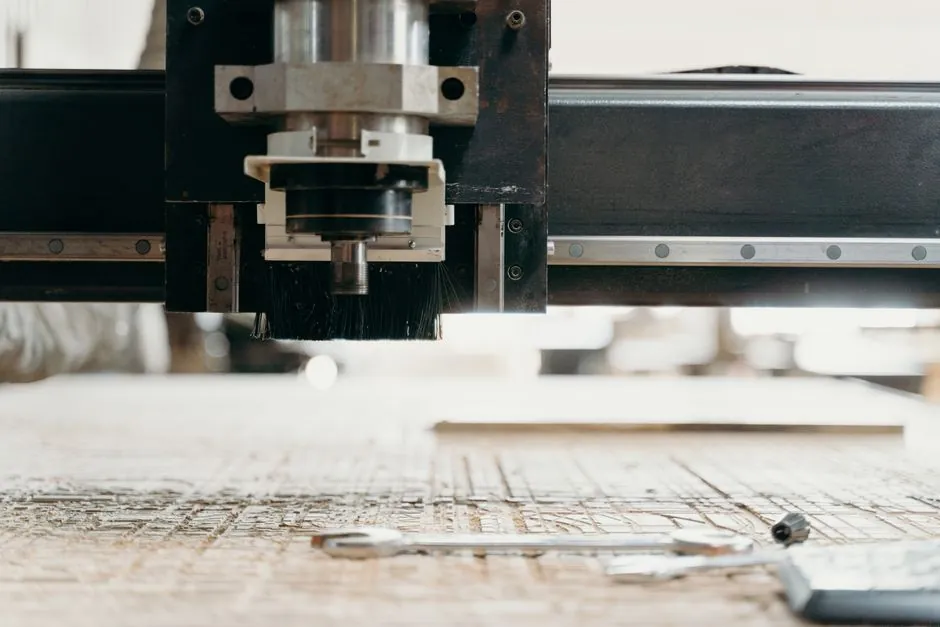
Inline optical inspection can measure more than 500 automotive features in a 15-second cycle, while CMM sampling may require hours to inspect about 150 spot welds on one body assembly [S1].
The practical choice is not a technology contest: inline metrology improves part-to-part coverage and feedback speed, while a coordinate measuring machine remains the stronger reference method for flexible contact probing, datum-based alignment, and complex geometry validation [S2][S4].
Decision criteria: coverage, cycle time, geometry, and integration
Coverage and feedback speed favor inline systems. The cited in-line implementation inspects more than 500 features per station cycle in 15 seconds and integrates directly with PLC pass/fail routing, which reported a 10% increase in jobs per hour [S1]. CMM sampling is slower by design because the part leaves production and each point is acquired through sequential probing [S2].
Geometry capability still favors the CMM. A CMM measures X, Y and Z points with a physical probe and derives dimensions, flatness, roundness, concentricity and positional relationships from those points [S2][S4]. Inline optical metrology extracts dimensions from image data and can replace the stylus at defined production locations, but it is not an unrestricted substitute for arbitrary probing [S3].
Integration effort is a separate criterion. An inline station requires optical acquisition, a digital reference, feature extraction, PLC communication and production-cycle calibration. One patent-based deployment describes a camera field of view covering at most 20% of a robot motion envelope, with encoder-synchronized strobing used to acquire images while the camera remains in motion [S3].
For high-volume machining, specify inline metrology when the part family is stable and critical dimensions can be observed from fixed viewpoints. Specify a CMM when every part may present different probing challenges, when manual datum alignment is acceptable, or when offline measurement is needed to investigate a failure rather than merely reject it [S2][S4].
Where inline metrology performs best
Inline metrology fits repetitive machining lines with controlled geometry, lighting, workholding and CAD definition. The described digital-twin alignment method uses 3D camera data and a digital reference model to check presence, location and feature quality without physical holding fixtures, and its published example reports sub-millimeter accuracy [S1].
Optical measurement also removes stylus contact, reducing the risk of marking or deforming the workpiece. Machine-vision metrology replaces discrete mechanical touches with image-based dimensional extraction, which is useful when cycle time prevents sequential probing of every part [S3].
The architecture does not have to require a stopped spindle and a stopped camera. A fly-mode arrangement can latch linear-encoder position at image capture and use a synchronized strobe to freeze motion, while an image-stacking technique can derive surface height from the Z position where a region reaches peak focus [S3]. For surface reflection and low contrast, the patent review describes image enhancement and local-extremum analysis, but production validation must establish performance on the actual alloy, finish, coolant condition and lighting geometry [S3].
Use inline metrology for first-piece-to-production conversion, machining drift detection, and stable high-volume families. Do not treat a reported 500-feature, 15-second result as a universal rating: feature count, geometry, camera count and compute latency determine whether a real cell can sustain that cycle time [S1].
Where CMM sampling remains necessary
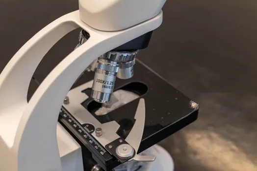
A CMM remains appropriate when the inspection task includes variable probing directions, deep or internal features, complex surfaces, or measurements that cannot be reduced to a fixed optical view. Its probing system records contact points in the machine coordinate system, while software aligns the part to datums specified by the drawing [S2][S4].
CMM sampling is also the better method for process qualification, first-article inspection, reverse engineering, calibration and investigation of intermittent defects. A published automotive example describes approximately 150 spot welds requiring multiple hours of CMM inspection, demonstrating both the value of comprehensive contact probing and its poor fit for per-part production surveillance [S1].
The structural choice matters less than the part envelope and accuracy demand. Bridge CMMs suit moderate-sized parts, cantilever machines provide access from three sides but lose stiffness at extended reach, gantry systems address large heavy parts, and horizontal-arm machines suit sheet metal and vehicle bodies with reduced precision relative to bridge systems [S2]. Selection should be based on tolerance bands, part mass, environmental control, measurement complexity and tests performed on representative parts [S2][S5].
For a stable family, sampling should not be treated as adequate dimensional proof for every produced part. The defect escapes batch sampling until the sample is measured, while inline inspection can place feedback before the next machining step. Set sampling frequency from process behavior and escalation rules rather than relying on a fixed percentage. The related guide on setting production sampling intervals from process dynamics provides the statistical context for that decision.
Failure modes and measurement-validity constraints
Inline optical metrology can fail through incorrect alignment, unstable illumination, reflective surfaces, low feature contrast, vibration, camera calibration drift, coolant or chip interference, and a mismatch between the production model and the as-built geometry. The reviewed patent set addresses several variables, including illumination transfer between machines of the same type, but such procedures still require verification under local plant conditions [S3].
CMM measurement can fail through probe contact variation, fixturing movement, operator-dependent probe programming, stylus access limits, and thermal effects. Contact probing is particularly unsuitable for soft surfaces because deformation changes the measured geometry, while sequential point acquisition consumes cycle time [S2].
Neither method is automatically metrology-grade for the whole part. CMM capability must be tied to the specific tolerance, feature size, part material and uncertainty budget. Inline capability must be tied to the actual camera, optics, lighting, algorithm, calibration method, environmental conditions and production CTQs [S1][S3].
Use CMM correlation as part of inline validation. Measure a representative set of parts on the CMM, compare dimensions against inline results, quantify bias and repeatability, and define an action limit for process drift. Do not accept a supplier accuracy statement without a correlation study on production parts under thermal load, vibration, coolant exposure and expected part variation.
Practical selection workflow and standards

Start with the feature list. Classify each dimension as optical-visible, mechanically probed, GD&T relationship, datum-dependent or difficult to access. Then compare options on four criteria: coverage, cycle time, geometry flexibility and integration effort. Inline wins on coverage and feedback, while CMM wins on probing flexibility and offline traceability. [S2]
For a typical high-volume machined component, use inline metrology for continuous monitoring of a limited set of stable critical dimensions and combine it with periodic CMM checks for broader geometry, datum relationships and process validation. For a low-volume, high-mix family, use the CMM as the primary method because fixed optical stations are difficult to justify and can require a new view for each part number [S2][S4].
CMM records support dimensional, relational and as-manufactured geometry documentation, first-article inspection reporting and compliance with drawing, customer or industry requirements [S5]. ISO 9001 governs quality-management-system requirements, while ISO 14253-1 addresses decision rules for verifying conformity or nonconformity with specifications, but neither standard alone establishes that a CMM or optical system is accurate enough for a particular tolerance. These capabilities still depend on the equipment specification, calibration and measurement uncertainty.
The final acceptance test should use production-representative parts, at least three operators for manual CMM work if applicable, multiple production shifts, and the actual fixture and machine conditions. Track feature coverage, measurement uncertainty, false reject rate, false accept rate, cycle time, calibration interval and correlation to the CMM. The best architecture is usually a two-layer system: inline metrology for speed and CMM sampling for flexible validation.