Electrical panels should receive infrared thermography at least annually, with quarterly or semiannual scans used when failure consequences, operating changes, or loss history warrant shorter intervals [S1][S3].
The inspection is typically performed while equipment is energized and operating under normal load, which allows the camera to capture temperature differences that may not be present when equipment is shut down [S5].
Annual Baseline for Electrical Maintenance
As of January 2023, NFPA 70B became the recognized NFPA 70B Standard for Electrical Equipment Maintenance, and the 2010 edition of NFPA 70B recommended routine infrared inspections of energized electrical systems annually prior to shutdown [S1][S3]. The standard addresses preventive maintenance for electrical, electronic, and communication equipment and is used with NFPA 70 and NFPA 70E [S1].
That annual frequency does not make infrared thermography a substitute for other maintenance. NFPA 70B does not supersede or duplicate manufacturer recommendations, and the thermal survey remains one diagnostic layer within a broader preventive-maintenance program [S1][S5].
For a panel owner, the practical baseline is therefore one documented scan per year under representative operating conditions. A scan performed after an outage, with the panel lightly loaded, may not reproduce the thermal conditions needed to compare connections and equipment [S3].
When to Use Quarterly or Semiannual Intervals
Shorter intervals are justified by loss experience, installation of new electrical equipment, or changes in environmental, operational, or load conditions [S3]. Semiannual inspections are also prudent where an unscheduled failure could cause significant environmental or safety harm or catastrophic damage to connected systems [S3].
Three decision signals support moving from annual to semiannual inspection: high-consequence loads, demonstrated thermal defects, or repeated operational change. Quarterly scanning is justified when the site can name a specific reason that annual coverage would not detect deterioration soon enough, such as recurring overload history or frequent changes in demand [S3].
Environmental conditions also matter. Equipment operating outdoors, in high ambient temperatures, or in corrosive or dusty installations can require closer monitoring than the annual baseline. The interval should be set by equipment condition and service consequences, not copied mechanically from another facility [S3].
Compare the Main Inspection Methods
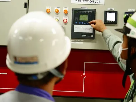
The decisive variables are fault visibility, worker exposure, frequency, and diagnostic quality. A thermography inspection of a panel cannot be performed without removing the cover unless an inspection window rated for arc-flash hazards is used [S4].
Scan Under Representative Electrical Load
An effective survey is performed while equipment is energized and operating under normal load, not while it is shut down [S5]. This condition exposes the temperature differences that can indicate a loose connection, overloaded circuit, failing component, or another developing fault [S5].
Panels, switchgear, breakers, disconnects, motor control centers, transformers, bus ducts, and electrical connections are all established thermography targets [S5]. Within a panel, the assessment should cover the equipment that can show meaningful thermal behavior, including fuses, breakers, terminal strips, conductor terminations, disconnects, and any other components visible to the camera [S4].
Seasonal systems may require surveys on several dates across the calendar year because heating, cooling, and changing operating loads alter the conditions under which defects become visible [S3]. A single midday image cannot substitute for load history, and a recurring scan program allows maintenance teams to compare the same component over time [S3][S5].
Prepare a Traceable Panel Inspection Route
“Routine infrared inspections of energized electrical systems should be performed annually prior to shutdown” is the stated inspection requirement in the 2010 edition of NFPA 70B quoted by the maintenance review [S3]. The operative word is “energized,” because the survey needs operating equipment to produce meaningful thermal patterns [S3].
Each route should identify the panel, enclosure, component, phase or conductor where applicable, load condition, ambient conditions, and camera identification. Include breakers, fuses, terminal strips, conductor terminations, and visible external disconnects in the component list rather than limiting the route to one device type [S4].
The report should retain thermal images, reference photographs, component locations, temperature differences, abnormal heat patterns, possible causes, and follow-up actions [S5]. Recurring images also create a baseline: a rising temperature difference or changing distribution across the same termination can justify corrective maintenance before a visible failure appears [S5].
Use Arc-Flash-Rated Windows for Routine Scans
An infrared window can make repeated panel scans safer and less disruptive by avoiding cover removal, but an unrated opening or ordinary plexiglass installation is not acceptable for arc-flash protection [S1][S4]. The window must carry a rating appropriate to the equipment and exposure risk before it is used as part of a routine thermography route [S4].
Installations differ in observability. Switchgear circuit breakers that are externally visible can be scanned without looking through an enclosure window, while concealed busbars, internal wiring, and terminations require an approved viewing path [S4]. IR windows reduce recurring inspection downtime and can allow lower PPE levels than energized open-panel inspections, but they do not remove electrical-safety requirements [S1].
For broader comparison with permanent monitoring methods, see Busbar and Breaker Temperature Monitoring: Sensors, Standards, and 2026 Field Data.
Correct the Cause, Then Preserve the Evidence
Thermography identifies abnormal heat patterns, but diagnosis still requires electrical knowledge and follow-up inspection [S2][S5]. Loose connections, overloaded circuits, imbalanced loads, corrosion, and defective components are possible failure modes that can produce distinct thermal signatures [S1].
A single elevated reading should not be treated as a universal trip value. The comparison must consider similar components, load, ambient temperature, and the historical pattern; a cabinet sensor that only announces a setpoint may miss a single termination running hotter than its peers [S4].
After correction, rescan the same component under comparable load and retain the before-and-after images. This closes the maintenance loop, verifies that the thermal anomaly was corrected, and establishes the next comparison point for annual, semiannual, or quarterly scheduling.
The next controllable action is to issue a panel-by-panel route with a 12-month baseline, flag every high-consequence or frequently changed installation for six-month review, and reserve quarterly scans for documented defect history or operating conditions that specifically require them [S1][S3].