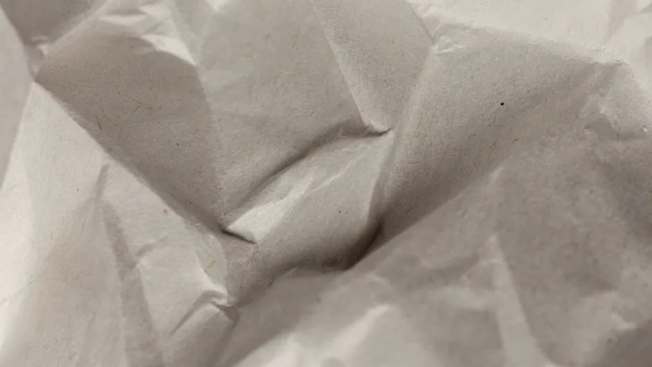
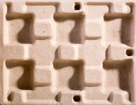
Machined aluminum mold bases handle the bulk of short-run and prototype pulp forming because they machine fast, drain water through etched or drilled channels, and cut rework time versus hardened steel [S1].
For high-volume egg tray, fruit tray, and protective insert production, tooled steel mold bases deliver the wear life needed at 6-10 cycles per minute, with steam-heated platen geometry that survives millions of cycles [S2]. Mesh-sieve forming tools sit in a third lane, where the mold body is a fine metal screen rather than a solid machined surface [S6].
Material Selection: Aluminum vs Steel vs 3D-Printed Rapid Tooling
Pulp mold bases divide into three material lanes, and each one trades off against cycle count, surface finish, and drainage. The dominant commercial materials for pulp and paper mold bases are aluminum and steel, with steel preferred for its strength and wear resistance on long runs [S1]. Aluminum cuts faster in the machine shop, weighs roughly a third of an equivalent steel base, and sheds heat quickly, which matters when steam-chest curing is part of the line.
Additive manufacturing has opened a third lane for the prototyping and bridge-to-production stage. A 2020 study validated a metal additive manufacturing process chain for paper-product molding, including the production of micro features 300 micrometers wide in high aspect ratio, a feature size that conventional tooling struggles to deliver [S3]. FDM-printed polymer molds are used upstream as design-validation and bridge tooling, accepting lower cycle counts in exchange for cutting hard-tool lead time on the same part geometry [S5]. The decision rule is straightforward: prototype on FDM, validate on metal AM, and commit to machined aluminum or hardened steel once the part number locks.
Forming Technique Compatibility: Wet Press, Dry Press, and Vacuum/Overpressure
The mold base is only half the problem; the forming method dictates the surface, drainage, and heating geometry that the base must carry. Pulp molding splits cleanly into wet pressing and dry pressing, with wet pressing driving a fiber-water slurry into the mold and drying it in place, while dry pressing compacts pre-dried pulp under high pressure for faster throughput on long runs [S1].
On the production equipment side, Danielewicz's 2025 review in BioResources documents both vacuum forming and overpressure (pressurized air) forming, alongside hydraulic molding methods used since the 1950s, as still-current principles of operation for form-molded pulp products (FMPPs) [S2]. Vacuum forming demands uniform micro-perforation across the tool face so suction holds fiber evenly; overpressure forming pushes from the back side and tolerates a coarser drainage pattern. A mold base machined with a drilled-and-etched drainage lattice, or built as a fine metal sieve body, suits the wet-press and vacuum path; a denser, heated solid base suits the dry-press and overpressure path [S6].
Slurry Chemistry, Fiber Choice, and Mold Surface Requirements
Fiber selection drives mold surface requirements, because the slurry that flows over (or through) the tool is abrasive and chemically active. Bagasse, bamboo, and recycled paper are the three most cited fiber sources for molded pulp products, with bagasse valued for durability, bamboo for moisture resistance, and recycled paper for waste-stream economics [S1]. Each fiber cuts the tool surface differently: bagasse and mechanical-recycled paper carry fines and silica that erode polished aluminum fast, so production tooling for those slurries typically specifies hardened tool steel or hard-anodized aluminum.
Secondary and primary papermaking pulps, plus other waste intermediates, are explicitly identified as the raw-material base for FMPPs, with the choice of intermediate directly linked to the cost structure of unit operations [S2]. That means a mold base designed for clean virgin pulp cannot be assumed compatible with a bagasse or post-consumer waste furnish without checking drainage geometry, because fines loading and freeness both change. The encyclopedia entry on mold bases maps the broader category context, while casting mold pages detail how the same surface-finish logic applies when the same machine shop is asked to quote both pulp and metal tooling.
Selection Criteria: Pressure, Cycle Count, Drainage, and Surface Finish
Four criteria decide between aluminum, steel, and mesh-sieve mold bases for a given pulp and paper application: forming pressure, expected cycle count, drainage requirement, and required surface finish. For low-pressure wet pressing at under 5 bar, machined 6061 or 7075 aluminum with a hard-anodized surface is the workhorse choice and is the standard recommendation for prototype and short-run pulp tooling [S1]. For high-pressure dry pressing and overpressure forming at 6-10 bar, P20 or H13 tool steel with polished cavity surfaces is specified to keep dimensional drift under control across multi-million-cycle runs [S2].
For parts where surface cosmetics do not matter, such as industrial egg trays and agricultural fruit trays, fine metal sieve mold bodies (forming mesh) are an alternative, and the forming step takes place by immersing the sieve tool into the pulp slurry, with 10 g of paper fiber per liter of water cited as a working consistency for batch forming [S6]. For visible or food-contact parts, a closed-surface machined base with controlled micro-drainage is mandatory because open mesh leaves a telemark on the part. The 300-micrometer micro-feature benchmark from the 2020 rapid-tooling study is a useful reference for the smallest repeatable drainage hole the production line will tolerate without fiber buildup [S3].
Prototyping Workflow: FDM Bridge Tooling and Metal AM
Two prototyping routes are documented for pulp mold bases, and both compress the design-to-part loop compared to conventional tool-steel machining. FDM tooling supports the design validation stage by allowing porosity, parting lines, and ejection features to be checked at low cost before any hard-tool steel is ordered, and it serves as a bridge to hard tooling on the same geometry [S5]. For pulp-mold prototypes, FDM prints are sometimes used as a heavy solid pattern, then overwrapped with anti-insect mesh, which then acts as the actual forming surface [S4].
Metal additive manufacturing, specifically micro-metal AM process chains, has been benchmarked against sintered tooling and against conventional tooling for paper-mold production, with the rapid-tooling chain shown to outperform sintered tools on micro-feature reproduction and lead time [S3]. The trade is part cost per mold versus lead time: a sintered or cast bronze base is cheaper but cannot reach 300-micrometer micro-features; a metal AM base matches the micro-feature spec at a tooling cost 2-3x higher but with a lead time measured in days, not weeks. This makes metal AM the right call for short-run production tooling and for design-of-experiment work on a new fiber furnish, where iterating the drainage pattern is the entire point.
Failure Modes, Constraints, and What the Mold Base Will Not Fix
Three failure modes dominate pulp and paper mold base complaints, and most of them are not solved by changing the base material. Surface scoring from abrasive fiber is the first, and it shows up as loss of surface finish and as contamination in the part, not as a tool breakage; the fix is harder tool steel, hard anodizing, or a plating step, not a different base alloy [S1]. Drainage fouling, where fines plug the micro-holes or sieve openings, is the second, and it forces frequent acid-wash cleaning cycles that themselves attack aluminum faster than steel [S2]. Warping of large-area bases from repeated steam-chest cycles is the third, and it is a function of base thickness and rib pattern more than of base material, so a 25-30 mm thick ribbed steel base outperforms a 40 mm solid aluminum base on flatness stability over a million cycles.
Material selection cannot fix a part-design problem. If the part has undercuts that the mold cannot release, no alloy change resolves it; the geometry must change. If the part has variable wall thickness, the dry-press forming pressure will bias fibers toward the thin regions, and the mold base cannot redistribute that. For a spec-first procurement workflow on a new pulp part, a useful gate is to lock fiber furnish, target cycle count, and forming method before quoting the mold base, because swapping any one of those three after the tool is cut means re-cutting the tool. Adjacent context for a wider packaging and equipment spec walk is mapped in the stretch film selection spec map for apparel distribution, where the same spec-first gating logic applies to downstream palletization rather than upstream forming.
Trackable Signals Worth Watching Next

Two signals are worth watching on a 3-6 month horizon for anyone specifying a pulp and paper mold base. First, the BioResources review line on biodegradable barrier aids for FMPPs is active: improving barrier properties to push pulp into food-contact and beverage-bottle roles is the named development vector [S2], and barrier coatings change mold surface requirements because coated parts need a release agent or a polished surface. Second, the rapid-tooling process chain for paper-mold micro-features is now an established alternative to sintered tools [S3], so a follow-on study on cycle-count durability of metal AM pulp tooling under production slurry conditions would be a high-value next data point. Until that lands, the working rule from the 2020 process-chain study is that metal AM wins on lead time and micro-feature accuracy for runs under six figures, and tooled steel wins on life-cycle cost above that.
For component-level specifications, see sand casting mold.