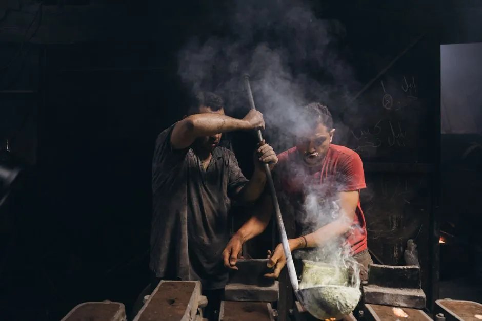
Sand casting is the workhorse process for metal parts ranging from about 20 g up to several hundred tonnes, with flask (mould box) dimensions setting the hard upper limit for green-sand work and grain size plus binder system driving surface and tolerance outcomes [S1].
Selection hinges on four variables: required part weight and footprint, alloy and pour temperature, target linear tolerance, and annual volume, all of which interact with the binder system and the pattern tooling material the foundry commits to [S1][S2][S4].
Where Sand Casting Fits in the Process Map
Sand casting is the dominant share of metal castings produced worldwide each year, and remains the only process that scales from a one-off prototype to runs above 1,000,000 units per year for parts that are simply too large or too geometrically complex for die casting or investment casting [S1][S4].
Silica-based molding sand handles metal temperatures north of 3,000 °F (≈1,650 °C) and is reclaimed after every pour, which is why no other disposable-mold medium matches sand for thermal range, mechanical strength, and unit cost on heavy ferrous work [S4].
For buyers mapping process choice to part size, the practical envelope reads: roughly 20 g to several hundred tonnes per piece, with maximum wall thickness in excess of 100 mm and minimum wall thickness of about 3 mm for light alloys or 5–6 mm for steel and other ferrous alloys [S1].
Flask, Box, and Foundry Size Limits
Green-sand work is bounded by the flask or mould box, since the pattern and the packed sand must physically fit inside it; cupola and flask capacities at commercial foundries typically span small bench flasks (a few hundred mm per side) up to floor flasks measured in multiple metres per side for steel-mill and ship-building castings [S1].
Chemically bonded (dry-sand) systems are not bound by a single flask the same way: the mould can be built in sections, slings, or even as a pit pour in a foundry floor, which is what pushes sand casting into the multi-hundred-tonne range for press frames, rolling-mill housings, and large gear blanks [S1][S4].
Buyers should treat flask inside dimensions as the first cut on the datasheet; if the part envelope exceeds the largest flask a foundry can offer, the conversation shifts from green sand to no-bake floor moulding or to alternative processes such as investment casting or forging [S2][S4].
Three Process Variants on One Comparison Axis
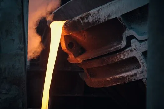
Green sand (clay-bonded, moisture-activated), dry sand / chemically bonded (resin or sodium-silicate set), and loam sand (high-clay, for very large simple shapes) cover essentially the entire commercial size and tolerance envelope, and the right pick depends on tolerance, surface, and volume rather than alloy alone [S1][S5].
On a 4-criterion comparison drawn from current foundry guidance: green sand wins on cost and lead time but loses on tolerance (typical ±1 mm with another ±1 mm across the parting line); dry sand / chemically bonded hits the better tolerance band (achievable ±0.4–0.5 mm plus 0.2–0.25 mm across parting lines and core joints) and surface finish down to 1.6 Ra, with 3.2 Ra and above more typical; loam sand is the niche choice for very large castings where high clay content keeps the mould stable and finish smooth but handling is harder [S1].
Surface finish numbers line up the same way: green sand commonly lands at 12.5–25.0 Ra, while chemically bonded systems routinely hit 3.2–6.3 Ra, and best-case chemically bonded work can drop into 1.6 Ra territory for critical sealing or hydraulic faces [S1].
Pattern Tooling and Volume Economics
Tooling material, not the mould itself, is usually the cost driver on short runs, and the three realistic options have published life brackets buyers can compare against annual volume [S1].
Polyurethane board tools machine quickly and tolerate late design changes, with a working life around 5,000 units; aluminium tooling raises tool life into the 50,000–100,000 unit range while still being easy to machine; machined steel or iron patterns are the long-run option for series above 100,000 units and are typical once the design is frozen [S1].
Sand casting's economic sweet spot sits between about 1,000 and 5,000 units per year before die casting undercuts it on per-piece cost, but for components that are too large, too thick, or too alloy-restricted for die casting, sand routinely remains the production process at over 1,000,000 units per year [S1].
Draft, Wall, Tolerance, and Allowance Numbers
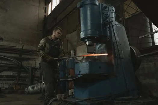
Draft angles of 1–5° are required on vertical faces; current best-practice tables break this down further as 1–2° on external walls, 2–3° in internal pockets, and 3–5° in deep cavities, with larger castings stepping to the higher end of each band [S1][S2].
Linear tolerance benchmarks separate achievable from typical: achievable ±0.4–0.5 mm with an additional 0.2–0.25 mm over mould parting lines and core joints (dry sand), versus typical ±1 mm with an additional ±1 mm over parting lines and core joints (green sand) [S1].
Machining allowance is sized at 0.5–1.6% of the linear dimension, which works out to roughly 1.5–6 mm in practice, and flatness is normally held to about 0.1 mm per 25 mm of length once localised pitting is excluded [S1].
For buyers who need a written reference, ISO 8062-1:2007 (vocabulary), ISO/TS 8062-2:2013 (rules), and ISO 8062-3:2007 (general dimensional and geometrical tolerances plus machining allowances for castings) are the relevant GPS series for tolerancing moulded parts [S1].
When Sand Casting Is the Wrong Pick
Sand casting is the wrong process when the buyer needs thin-wall aluminum die-cast features under about 3 mm, optical-grade surface finish on visible cosmetic surfaces, or tight tolerance on long thin webs that cannot tolerate the 0.1 mm per 25 mm flatness envelope, investment casting, die casting, or CNC-machined billet will beat it on those axes [S1][S2].
It is also a poor fit when the alloy is incompatible with standard silica sand chemistry, for example, certain highly reactive magnesium alloys require inhibitor-protected atmospheres or alternative mould media, and when lead time cannot absorb the 2–4% moisture-controlled green-sand conditioning or the cure cycle of a no-bake system [S4].
Buyers specifying linear guide rail bases, crossed roller guide carriages, or large construction machinery housings should default to sand casting for the structural body and to machined or ground stock for the raceways, because no disposable-mould process can hold the surface and flatness those motion components need.
Mold Materials, Binders, and the Foundry Specification

Most ferrous work uses round-grain silica sand sized between AFS 50 and AFS 80, with finer grain pushing surface finish up and coarser grain venting better and resisting thermal shock on heavy steel pours [S4].
Binder choice follows the tolerance and volume target: bentonite clay with 2–4% moisture for green sand; phenolic, furan, or sodium-silicate chemical binders for no-bake and dry-sand work where higher strength and tighter dimensional control justify the extra processing cost [S4].
Additives matter on heavy sections: sea coal, cellulose, and refractory wash coatings reduce burn-on, improve surface finish, and stop metal penetration into the sand on heavy steel and high-chrome iron pours, so buyers should ask which coating system the foundry runs for the specific alloy on the print [S4].
Shortlist Logic for the Buyer
Match the variant to the constraint that hurts most: pick green sand when annual volume is under about 5,000 units and the ±1 mm typical tolerance is acceptable; pick chemically bonded dry sand when surface finish must drop to 3.2 Ra or better, or when linear tolerance must hold inside ±0.5 mm; pick loam sand only for very large simple shapes where high-clay stability outweighs handling difficulty [S1][S5].
For procurement readers cross-checking capital-equipment references, the same flask-size and tolerance logic that governs mould base sizing on plastic-injection tooling also constrains a sand casting mold envelope, and the pattern allowances track closely to those used in any casting mold program, so the same DFM discipline carries across [S1][S2].
Track these signals on the next RFQ: the foundry's largest flask inside dimensions and the binder system it runs for your alloy; the pattern material it recommends and its published tool life; and whether its in-house machining can hold the ISO 8062-3:2007 tolerance grade the print calls for, since those three numbers collapse most of the selection work onto a single page.
For component-level specifications, see sand casting mold, casting mold, and linear guide.
This topic is covered further in Disc Coupling Selection for Steel Mill Drives: Spec Map.