
A test lead set is selected by the measurement environment, not by the multimeter label: a CAT III 1000 V lead used in a CAT IV panel sits below the energy available, while a 1 mm² conductor lead plugged into a CAT III instrument will not deliver CAT III performance, because the weakest component defines the system rating [S4]. Engineers who skip the five-criterion check typically see unstable readings, cracked insulation in cold rooms, or contact drift after a few hundred insertion cycles [S4].
Conductor count matters as much as cross-section: a 42-strand copper lead is rated for stable signal transmission at currents up to 10 A, while lower-strand alternatives in the same silicone jacket run hotter at the same current [S3]. The selection logic below is built around CAT rating, conductor size, insulation polymer, connector geometry, and length, the same five questions OEM buyers work through before a test lead order is released [S4].
CAT Rating: Match the Lead to the Energy Available, Not the Meter
CAT (Measurement Category) ratings are defined under IEC 61010 and describe the energy available at a measurement point, not the voltage limit of the instrument [S4]. The four environments commonly encountered are CAT I (electronics-level signal), CAT II (socket-outlet level, single-phase loads), CAT III (three-phase distribution, fixed industrial equipment), and CAT IV (utility service entrance, outdoor conductors), each requiring higher transient withstand at the same working voltage [S4].
A Fluke TL175 set typically reads around 0.5 Ω end-to-end on a bench check, and that is normal for a general-purpose lead: low-resistance probe designs such as the Probe Master 8150 retractable pogo-pin series and 8000-series fixed-tip leads trade a small resistance variation for a noticeably lower baseline than commodity leads [S5]. Field failures trace back to two errors: specifying only the connector while ignoring the CAT band, and assuming an instrument's CAT rating transfers to the attached leads without independent certification [S4].
Conductor Cross-Section and Strand Count
Conductor cross-section is sized to the maximum continuous current with a safety margin, and silicone-insulated 1.0–1.5 mm² copper is the typical baseline for 10 A general-purpose work [S3][S4]. A 42-strand copper bundle supports stable transmission up to 10 A and resists fatigue under repeated flexing better than lower-strand constructions, because each strand carries a smaller share of the bending strain [S3].
Lead resistance adds directly to the loop, so a 1.5 m lead that measures 0.5 Ω end-to-end drops 5 V at 10 A, which is enough to mis-read a 12 V battery by 40% if the operator forgets to subtract it [S5]. For low-resistance work below 10 Ω, 2-wire measurements suffer from contact and thermoelectric error sources, and a 4-wire Kelvin lead is the correct tool because it separates current injection from voltage sense [S5]. The takeaway for procurement: do not pair a 0.5 mm² lead with a 10 A clamp meter, and do not use commodity leads to verify sub-ohm shunts.
Insulation Material: Silicone, PVC, TPE

Silicone is the default for industrial and laboratory leads because it stays flexible from roughly −40 °C to 200 °C and resists the cracking seen in cold-storage or outdoor use [S4]. PVC is lower cost and adequate for indoor electronics benches where the temperature window stays near room temperature, but it stiffens below 0 °C and ages faster under UV exposure [S4]. TPE (thermoplastic elastomer) is the middle option, used when a buyer wants silicone-like flexibility at a tighter price.
Insulation thickness also sets the creepage distance to the conductor, which is part of why two leads with the same voltage rating can carry different CAT bands: a thicker, double-layer silicone jacket clears the clearance required for CAT IV, while a single-layer PVC jacket typically stops at CAT II or CAT III [S4]. For any lead that will sit on a shop floor near rotating machinery, silicone is the only sensible default.
Connector Geometry: Banana, BNC, Mini-Banana, and Modular
Connector choice is set by the instrument input and the test point, and the four formats cover most industrial work. A standard 4 mm banana plug is the default on most bench DMMs and on modular lead kits such as the Probe Master 9100 series, which is also manufactured in El Cajon, California and is compatible with Fluke, Simpson, and Tektronix meters [S2]. Mini-banana (2 mm) leads suit tight PCBs and SMD test points where a 4 mm tip would short adjacent pads, and SMD spring-tip micro-probe kits such as the Probe Master 9110 handle QFP and fine-pitch work [S2].
Tip style also changes contact quality: spring-loaded pogo tips maintain a steadier contact force on oxidized test points than fixed-tip designs, and retractable shrouds (for example, the Probe Master 8150 retractable series) add a layer of finger protection when the operator is probing live conductors [S2][S5]. A bench DMM used at a calibration bench does not need the same tip as a field electrician working a 480 V panel: pick the connector to the contact, not to the meter.
Lead Length, Resistance, and Reach
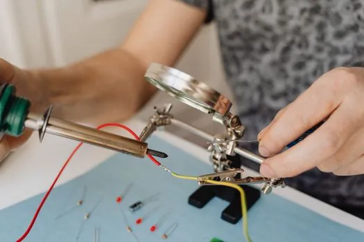
Length is a trade between reach and added resistance: a longer lead lowers operator exposure to arc-flash energy because the hands stay farther from the bus, but it also adds series resistance proportional to the gauge [S4]. A 3 m silicone lead of 1.0 mm² copper will read noticeably higher on a 4-wire milliohm check than a 1.2 m lead of the same gauge, and the difference becomes a measurement error on shunt calibration and on low-value resistor verification [S5].
For panel work, the practical maximum is roughly 1.5 m for general troubleshooting and 3 m for work behind a live cabinet where reach is mandatory. For lab bench work, a 1.0–1.2 m lead keeps the loop resistance below 0.3 Ω and gives the cleanest 2-wire readings on a calibrated DMM. Storage reels, such as the 30 ft retractable lead reel in the Probe Master catalogue, exist for long-run temporary signal pickup but are not the right tool for low-resistance verification [S2].
Who Should NOT Pick the Generic 1000 V Lead
Three groups are routinely mis-served by the commodity CAT III 1000 V lead that ships with most new DMMs. Calibration-lab technicians measuring sub-10 Ω resistors need a 4-wire Kelvin lead or a low-resistance pogo-pin design such as the Probe Master 8150, because a 0.5 Ω commodity lead is larger than the value under test [S5].
Field electricians working utility service entrances at 480 V or higher need a CAT IV-rated lead with a retractable shroud, not a CAT III bench lead, because the available short-circuit energy at a service entrance is higher than at a sub-panel [S4]. SMT and bench rework engineers probing 0.5 mm pitch QFP packages need a 2 mm mini-banana or an SMD spring-tip lead, because a 4 mm tip will bridge adjacent pads and short the device [S2]. Each case has a specific, named tool, and a "general-purpose" lead fails each one of them.
Comparison: Four Lead Families Against the Five Criteria
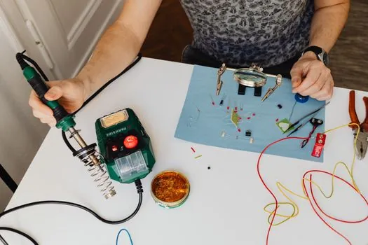
Four lead families cover the bulk of industrial and laboratory use, and a quick side-by-side against the five selection criteria is the cleanest way to shortlist. Standard silicone 1.0–1.5 mm² banana leads score well on flexibility and CAT III availability but read around 0.5 Ω end-to-end, which is too high for sub-ohm work [S3][S4][S5]. Modular kits such as the Probe Master 9100 series add interchangeable tips, extending the lead across electronics, telecom, and automotive duty without buying a second set [S2].
Low-resistance pogo-pin and 4-wire Kelvin leads win on baseline resistance and on contact repeatability for calibration work, but the tip geometry is more delicate and the cost per set runs higher [S5]. Retractable-shroud CAT IV leads win on operator safety for utility-side work and on cold-storage flexibility, but the retractable mechanism adds moving parts and they are not optimised for tight-pitch PCB probing [S2][S4]. The shortlist logic: pick by the worst-case energy environment first, then by the lowest-resistance measurement you will perform, and only then by connector type and length.
Standards, Compliance, and Pre-Purchase Checks
Test leads used in a live electrical environment fall under IEC 61010-031, which defines the measurement categories, the clearance and creepage distances for the connector, and the finger-protection geometry for the probe body [S4]. A compliant lead will carry both the IEC 61010-031 mark and the CAT band of the measurement point, and the two should match: a CAT III lead is not interchangeable with a CAT IV lead even at the same voltage [S4].
Before any purchase, a four-step check catches the bulk of mismatched orders. First, confirm the lead's CAT rating matches the highest-energy test point, not the meter's nameplate [S4]. Second, confirm the conductor cross-section supports the maximum expected continuous current with margin [S3][S4]. Third, confirm the connector type and tip geometry against both the instrument input and the contact at the test point [S2]. Fourth, confirm the lead length against the reach required, and check that added loop resistance will not exceed the measurement tolerance [S4][S5]. Buyers who work this list in order almost never return leads, and procurement teams stop receiving field-failure reports [S4]. For broader instrumentation context, see our electronic test measurement guide, and for related selection logic on adjacent measurement gear, see test leads on the encyclopedia and electronic test methods.
Related analysis: BESS Bill of Materials: Key Components, Spec Anchors, and Sourcing Map.
