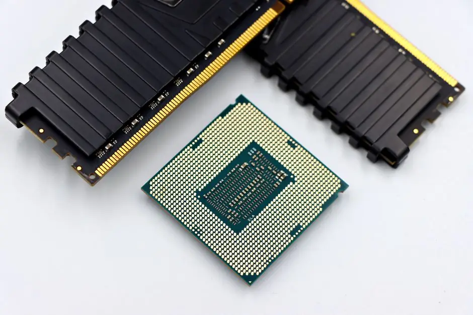
A grid-scale battery energy storage system (BESS) is built from seven functional blocks: battery cells, modules and racks, the battery management system (BMS), the power conversion system (PCS), the energy management system (EMS), thermal management, and the medium-voltage step-up transformer plus switchgear [S1][S4][S5]. Lithium-ion chemistry accounts for over 90% of the stationary storage market, with lithium iron phosphate (LFP) the dominant cathode because of its thermal stability and supply-chain maturity [S2][S4].
Specifying a BESS bill of materials (BoM) means fixing values for DC round-trip efficiency (typically 85 to 95% in lithium-ion systems), DC voltage window, C-rate, depth of discharge, ambient operating range, and the relevant safety listings, primarily UL 1973 for cells and modules, UL 9540A for cell-to-rack fire propagation testing, IEC 62619 for industrial lithium cells, and NFPA 855 for outdoor siting [S4][S5]. Procurement teams should treat those four standards as the non-negotiable gate before any cost negotiation.
Battery cells, modules, and racks: the BoM anchor
The battery pack is the single largest cost and weight block in any BESS BoM, and is built as a three-tier stack: cells in series/parallel form modules, modules form racks, and racks are wired into strings [S3][S4]. Most modern BESS use prismatic LFP cells in 280 to 314 Ah formats, with module voltages of 50 to 60 Vdc and rack voltages of 1000 to 1500 Vdc being the current industry convention for utility-scale builds [S4][S8].
Inside each cell, four sub-components define behaviour: anode, cathode, separator, and electrolyte, and the choice between LFP, NMC, NCA, sodium-sulfur, vanadium flow, and emerging lithium-sulfur chemistries shifts cost, energy density, and cycle life in measurable ways [S2][S3]. [LFP cells offer longer cycle life and lower thermal runaway risk, NMC and NCA cells offer higher energy density per kg, flow batteries decouple power and energy ratings via separate electrolyte tanks] is the cleanest trade-off for procurement teams weighing cost against footprint [S2].
For raw-material exposure, the LFP supply chain now leans on Chinese cathode active material producers, with downstream pressure covered in detail in our BESS raw material sourcing 2026: LFP prices, supplier tiers, spec gates write-up, and the cell-level cost driver for 2026 has been battery electrolyte tightness, not lithium carbonate price. Quality control at the cell level should require lot-traceable UL 1642 cell certificates and factory audit data on formation cycling before cells leave the supplier.
Battery Management System (BMS): the safety brain
The BMS is a three-tiered architecture consisting of battery monitoring units (BMUs) at the cell level, string BMS modules (SBMS) supporting up to 60 BMUs each, and a master BMS (MBMS) at the rack or container level [S4]. The BMU measures per-cell voltage, current, and temperature; the SBMS aggregates and balances; the MBMS handles pack-level state of charge (SoC) and state of health (SoH) estimation and interfaces with the PCS and EMS [S4][S6].
Functionally, the BMS must enforce overcharge and overdischarge cutoffs, cell balancing, thermal runaway early warning, and isolation fault detection, all of which are now baseline requirements under UL 1973 and IEC 62619 [S4]. Buyers should require the BMS to expose SoC, SoH, and individual cell voltages over Modbus TCP or CAN to the EMS, since proprietary protocols lock the site into a single vendor for the entire operational life of the asset.
Redundancy specification matters more than software features: dual redundant MBMS controllers, isolated BMU daisy chains, and independent contactor drivers are the three hardware items that separate a field-proven BMS from a marketing-grade one [S4][S6].
Power Conversion System (PCS) and step-up transformer
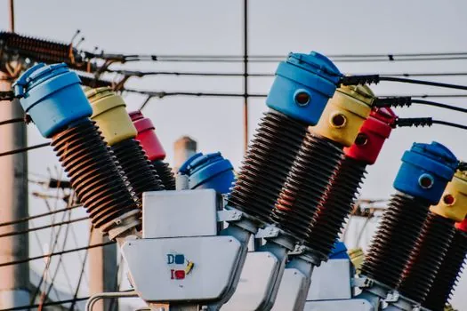
The PCS is a bidirectional inverter that converts the DC output of the battery string to grid-synchronised AC, and is sized in kW or MW per unit, with utility-scale blocks commonly delivered at 1.0 to 3.7 MW per skid [S4][S8]. Two architectural choices matter at procurement: AC-coupled BESS (separate PV inverter and BESS inverter) versus DC-coupled BESS (shared hybrid inverter), and the latter typically wins for new-build solar-plus-storage sites because round-trip efficiency improves by 2 to 4 percentage points [S4].
For the AC output side, the medium-voltage step-up transformer adapts the PCS low-voltage AC output to the grid interconnection voltage, typically 13.8 to 34.5 kV in North American distribution systems [S1][S8]. Spec gates here include IEEE 1547 inverter compliance, UL 1741 supplement for grid support, and transformer impedance of typically 5.75 to 7.5% to limit short-circuit contribution during faults.
Energy management system (EMS) and SCADA hardware sit on the same control network as the PCS, and procurement teams should require the EMS to expose IEC 61850-7-420 or DNP3 points to the utility SCADA before contract signature, otherwise grid interconnection testing will slip. At the BoM line level, the PCS-plus-transformer block typically represents 15 to 25% of the total BESS equipment cost, second only to the battery pack itself.
Energy Management System, thermal management, and safety hardware
The EMS is the site-level controller that decides when to charge, discharge, and at what power, and is distinct from the BMS, which only manages the battery [S4][S5]. A utility-grade EMS handles day-ahead and real-time dispatch, SoC-aware degradation hedging, and interfacing with the SCADA stack via Modbus TCP, IEC 61850, or DNP3 [S4][S8].
Thermal management on utility-scale BESS is almost universally liquid cooling for new builds, with refrigerant-assisted air cooling still used in some C&I containers, and the design point is keeping cell delta-T below 5 degrees C across the rack to prevent accelerated degradation [S4]. Specs to lock in are coolant type (typically a water-glycol mix), flow rate per rack, and a leak detection sensor at every tray.
Safety hardware adds another measurable layer: gas detection (H2, CO), aerosol or clean-agent fire suppression sized to NFPA 855 spacing rules, deflagration panels on container walls, and a UL 9540A-tested cell-to-rack fire propagation report are the four items auditors will check first [S1][S4]. The container enclosure itself is typically a 20 ft or 40 ft ISO frame, and the storage rack and storage cage sub-assemblies inside the container are the items most often under-scoped at the BoM stage, so they deserve their own line items rather than being bundled into a generic "container" cost.
Side-by-side component comparison for BoM decisions
For a procurement engineer building a 100 MWh utility-scale BESS in 2026, the four most consequential BoM line items compare as follows across the criteria that drive spec acceptance: battery cells, BMS, PCS, and EMS-plus-transformer [S1][S4][S5]. On cost weight, the battery pack dominates at roughly 55 to 65% of equipment cost, the PCS-plus-transformer block runs 15 to 25%, the BMS and EMS combined run 3 to 5%, and thermal plus safety run 5 to 10% [S4][S8].
On long lead time, battery cells and the step-up transformer are the two critical-path items at 16 to 32 weeks each, while the BMS and EMS are typically off-the-shelf at 4 to 8 weeks [S4]. On certification risk, cells carry UL 1973 and IEC 62619 obligations, the PCS carries UL 1741 and IEEE 1547, the transformer carries IEEE C57 and DOE 2016 efficiency rules, and the BMS carries functional safety evidence under UL 1973 [S4][S5].
On the criterion of vendor lock-in, the EMS and SCADA layer has the longest contractual shadow, because switching EMS vendors after commissioning typically requires a full firmware re-validation against the BMS, and a comparison of energy meter and revenue-metering points should be written into the EMS scope at bid stage, not after commissioning.
Failure modes, operational constraints, and known field events
The November 2024 DOE/INL Battery Energy Storage Systems report catalogues the architectural failure modes that procurement specs should explicitly mitigate: sensor drift, BMS communication faults, inverter overcurrent trips, thermal runaway propagation between cells, and transformer overpressure events [S1]. Two high-profile field events, the Moss Landing facility thermal runaway event in California and the WECC heat event in the western US, are the documented reference cases for why UL 9540A large-scale fire testing is now treated as a non-optional spec gate rather than a checkbox [S1].
Operational constraints that should be written into the BoM spec: ambient operating range of -30 to +50 degrees C for outdoor containers without active climate skids, humidity tolerance above 95% non-condensing for coastal sites, and seismic qualification to IEEE 693 high-level for California and Pacific Northwest projects [S1][S4]. Each of these is a documented driver of either warranty denials or interconnection delays if not baked into the BoM before bid. EPCs that under-spec the thermal skid in pursuit of a cost win on the EMS line typically pay for it in the first heat-dome summer after commissioning.
One operational risk worth flagging: the storage handling workflow at site delivery is where cells most often get dropped or punctured before energisation, and procurement specs should require sealed-road delivery, tilt-watch indicators, and a Pre-Shipment Acceptance Test (PSAT) witnessed at the supplier site, not at the project site.
What BESS BoM spec is for, and what it is not for
A 2026 BESS bill of materials spec is for utility-scale developers, EPCs, and C&I integrators who need a defensible cost-and-compliance map before issuing an equipment PO, and for procurement teams who have to back-justify spec gates to a lender or off-taker [S1][S5]. It is also for inverter and energy management platform vendors building their own integration playbooks, since the BoM tells them exactly which external interfaces they have to honour [S4].
It is not for residential behind-the-meter storage builders, who should be working from a much simpler BoM focused on a single hybrid inverter, a wall-mounted LFP pack, and a vendor-supplied EMS app. It is also not a substitute for site-specific interconnection studies, which sit outside the BoM entirely and are governed by IEEE 1547.1 and the local utility's tariff. For buyers looking to cross-check cell-level raw-material exposure, our BESS raw material sourcing 2026 coverage maps the supplier tier structure and spec gates in detail. For adjacent infrastructure bottlenecks, the power grid supply chain primer covers step-up transformers and switchgear at a system level.
Trackable signals over the next reporting cycle: UL 9540A test data releases from tier-1 cell vendors, IEEE 1547-2018 amendment activity on grid-forming inverter compliance, and any new NFPA 855 spacing amendments for outdoor containerised BESS. Two supply-chain nodes to watch: Chinese LFP cathode exports and the step-up transformer lead-time book, which together gate most 2026 project delivery dates.