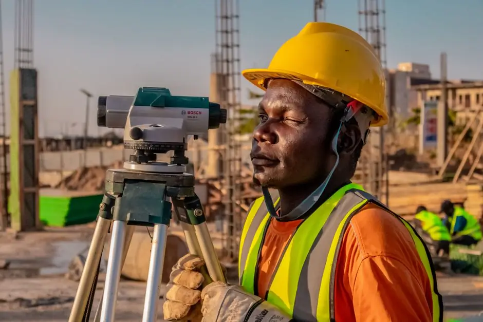
On an automatic level, the circular (bull's-eye) bubble is centred with the three foot screws first, then verified by rotating the instrument 180 degrees; the standard correction is to remove half the residual displacement with the case adjusting screws, re-level, and re-check at 90 and 360 degrees, per the NGS-issued Topcon DL-101 service note [S1].
That two-stage routine is the only way the suspended-mirror compensator stays inside its working range; on a DL-101, exceeding the range triggers the "Cmpe Err" message in the display, which is the clearest on-instrument indicator that the circular bubble has drifted out of adjustment [S1].
Why a circular bubble on a self-levelling instrument at all
An automatic level is "self-levelling" only within a limited tilt window of its internal compensator, typically on the order of ±10 to ±15 arc minutes for the common automatic (also called automatic level) optical design; outside that window the compensator bottoms out and readings become a function of instrument tilt [S5].
The circular bubble's job is therefore not to deliver the final line of sight, but to bring the line of sight close enough to true that the compensator can do the fine work; the manual says explicitly that the bull's-eye bubble should be kept in good adjustment to assure the working range of the compensator is maintained [S1].
Engineers should not confuse the two vials: the bulls-eye (circular) is a coarse, two-axis level used to put the compensator in range, while the tubular (linear) vial, when fitted, is the sensitive level used for precise measurement; survey instructors and textbooks universally state that you "level approximately, using the circular bubble, and then precisely, using the single sensitive" vial, in that order [S3].
Pre-check: tripod, tribrach, and the three-screw geometry
Before the bubble is touched, the tripod head has to be roughly level: legs set so the head looks level, telescope at a comfortable eye height, clamps tight, no leaning on the tripod during work, and the instrument firmly seated on the tripod screw by hand, no tools [S4].
The levelling head itself has three parts: a top plate or tribrach that carries the circular level, three foot (levelling) screws, and a trivet that mates to the tripod head, and the circular bubble is mounted directly on the tribrach, not on the telescope [S2][S4].
Two-leg-downhill placement matters on sloping ground: two feet go on the downhill side and are pressed in with the surveyor's foot on the foot plate, the third leg is then moved until the head looks level, and the legs are clamped before the instrument is attached, because any slip at this stage invalidates everything that follows [S4].
The 180-degree reversal test, step by step
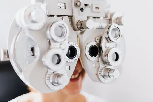
Procedure as documented in the NGS workshop handout for the Topcon DL-101 [S1]:
Step 1, centre the bubble in the bull's-eye circle using the three foot screws with the instrument in its starting orientation. Step 2, rotate the instrument 180 degrees about its vertical axis; if the bubble stays inside the circle, that axis is in adjustment. Step 3, rotate 90 degrees to check the perpendicular axis. A correctly adjusted bubble will stay inside the circle through a full 360-degree rotation [S1].
Where the bubble does drift, the correction is iterative and quantitative: turn the bottom-of-case adjusting screws (with the small pin supplied with the level) on the axis being checked, remove half the amount by which the bubble is out, re-level with the foot screws, rotate 180 degrees again, and re-check at 90 degrees, repeating until the bubble stays centred regardless of where the level is pointed [S1].
The "half the error" rule is the key engineering detail: the foot-screw-induced tilt and the residual adjustment error are separable only by halving, which is why a single pass of full correction over-shoots, and why a single pass of no correction simply re-asserts the bias, and the cycle is convergence-by-bisection on each axis [S1].
Rod bubble adjustment, the parallel problem
On a bar-code or invar levelling rod, the same circular bubble has to be in adjustment or every staff reading picks up a rod-plumb error, and the rod-side procedure is mechanically similar but optically driven [S1].
Set the rod on a stable point (a rod "turtle" or fixed pin), centre the bubble, and set up the level at a distance where most of the rod is in view; level the instrument. Use the level's tangent knob to align the vertical crosshair along one edge of the rod or invar strip, and check that the crosshair stays parallel to that edge top to bottom; if not, the rod-person trues the rod, accepts that the bubble will have moved off centre, and uses the adjusting pin on the screws beneath the bubble to recentre it without losing the crosshair-edge alignment [S1].
Then rotate the rod 90 degrees to the level, true it with the brace poles, recheck the crosshair-edge alignment, and re-centre the bubble with the adjusting screws; keep rotating and adjusting until the rod stays plumb and the bubble stays centred in all positions, recognising that the footplate contact point is rarely directly below the brace-pole pivot, so the rod will tend to walk out of plumb on reversal and must be re-levelled after every turn [S1].
Cadence matters: rod and instrument bubbles should be checked at least once a week, or any time the instrument or rod takes a knock or a drop, which is the same trigger most automatic-level manuals give for a compensator-pendulum check [S1].
Comparison of the two adjustment axes
Two axes behave differently and the field routine has to respect that, summarised against the criteria that actually drive the call:
Axis A, alignment with the line of sight: defined by sighting along the telescope; test is 180-degree reversal, correction is at the bottom-of-case screws on that axis, failure mode is "Cmpe Err" from the compensator running out of range [S1]. Axis B, perpendicular to line of sight: defined by rotating 90 degrees; test is 90-degree then 360-degree rotation, correction is at the second pair of bottom screws, failure mode is a heading-dependent staff-reading bias that does not show in any single sight-check [S1]. Sensitivity is identical in principle because both axes share the same vial, but in practice Axis A errors are easier to spot because the compensator saturates and alarms, while Axis B errors are silent and only show up as a closure error in a two-peg test or a levelling loop [S1][S5].
Selection of which axis to correct first is therefore a process choice: most field guides have you start with Axis A, because that is the axis whose failure is instrumented, then verify Axis B as a 360-degree no-drift condition [S1].
Common failure modes and what they tell you
Bubble drifts on 180-degree reversal but recentres after a half-error adjustment, then drifts again on the next reversal: the bubble vial itself is bent or the case screws are loose, and the unit should be bench-serviced rather than repeatedly field-corrected [S1].
Bubble stays centred through 360 degrees but the staff readings close poorly: suspect the tubular (sensitive) vial if fitted, or the compensator, not the circular bubble; the circular bubble is a coarse indicator only [S3][S5].
Bubble centres but the DL-101 still flashes "Cmpe Err" on a known-flat surface: the tribrach foot screws are within range but the compensator is mechanically out of adjustment, which is a workshop repair, not a field adjustment, and the manual warns that the bubble is only a precondition for the compensator, not a guarantee of its health [S1].
Bubble will not stay centred even briefly on a tripod that is leg-loose or set on soft ground: revisit the tripod setup before touching the instrument; the field guides are explicit that leaning on the tripod or having a leg slip will defeat any bubble adjustment [S4].
Sourcing, cadence, and what to log
The 180-degree reversal, half-error correction, 90-degree cross-check routine is the canonical procedure used in the U.S. National Geodetic Survey precise-levelling workshop material for the Topcon DL-101 [S1] and reproduced in standard texts; the rod-side procedure is the same workshop's method, with the addition of the crosshair/edge-of-rod optical truth-check rather than a second reversal alone [S1].
Manufacturers of automatic laser levels (Johnson Level, Engineer Supply) describe the same coarse-then-compensator logic, with the circular bubble centred to put the compensator in range, then the compensator holding line of sight against vibration, temperature drift, and operator handling [S2][S5].
Track these signals: weekly bubble check on every instrument and rod, post-impact check on the same day, and a two-peg test or loop closure whenever the instrument has been transported more than a short distance or stored for more than a month, with each adjustment and its date logged on the instrument card so that compensator-versus-vial errors can be separated over the service life [S1][S4].
Spec-level background on the components involved: circular saw, and automatic molding line.
For related coverage, see Carbide saw blade brazing and grinding line: capital cost breakdown 2026.
