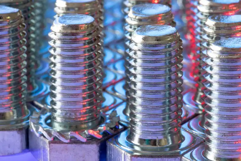
Capacitor discharge stud welding is a tip-ignition resistance-projection variant of stud welding that discharges a charged capacitor bank across a small ignition tip on the stud, melting the tip and a thin layer of base metal before spring pressure plunges the stud into the pool, with the entire cycle finishing in milliseconds [S2][S5].
Within CD, the two production variants are defined by how the arc is initiated: contact CD places the stud on the workpiece so that triggering the gun short-circuits through the ignition tip, while gap CD holds the stud at a defined, adjustable standoff above the workpiece and fires the capacitor bank as the spring-driven stud arrives at the surface [S2][S9]. That single mechanical difference drives weld time, suitable base materials, and minimum plate thickness, which is why the two methods are treated as separate processes rather than settings on the same gun.
Contact CD: stud-on-workpiece, ≤3 ms cycle, mild and stainless steel default
Contact CD uses a stud with a precision-machined ignition tip that is pressed against the base metal by the gun's spring, so the current path is closed through the tip the moment the trigger is pulled, and the rising current vaporizes the tip, ignites the arc, melts both faces, and the spring then drives the stud into the pool as the arc is cut [S2][S5]. One published process description states the entire cycle for contact CD completes in about 0.012 seconds (12 ms) including arc and plunge, with a process-level weld time of ≤3 ms for the arc itself [S1][S2].
The method is the default for stud diameters from M3 to roughly M10 (2 to 10 mm) onto thin sheets down to about 0.5 mm, where the recommended plate thickness rule is 1/10 d (one tenth of the stud diameter) with 0.5 mm as a hard floor [S2]. Contact CD is the more common of the two in shops that weld mild steel and stainless steel, where the higher melting point of the base metal tolerates the slower plunge [S3][S8]. The trade-off is reverse-side marking: contact CD's longer arc and slightly higher heat input relative to gap CD makes it less attractive on thin or coated sheet where the back side must stay clean, a constraint formalized in the "CD Stud Reverse-Side Marking Guide" used by CD stud suppliers [S5].
Gap CD: stud lifted to a defined standoff, ~1 ms arc, unlocks aluminum and brass
Gap CD holds the stud above the workpiece at a defined, adjustable distance and uses a solenoid or spring to accelerate it toward the surface; the capacitor bank fires as contact is made, so the arc is drawn while the stud is still moving, producing a shorter arc and a faster, harder plunge than the contact method [S2][S3][S9]. Published process data puts gap CD weld time at about 1 ms, roughly one-third the contact CD figure, with a reduced weld time overall of about half that of contact CD on the same stud [S1][S2].
The faster cycle is what makes gap CD the practical choice for aluminum, brass, and thin stainless sheet where contact CD either leaves a visible mark on the reverse side or fails to fuse cleanly [S2][S3]. Because the arc is so short and the heat input so low, aluminum can be welded without a shielding-gas atmosphere, which is the main reason sign manufacturers and electronics enclosures specify gap CD over contact CD [S1][S3]. Recommended plate thickness follows the same 1/10 d rule with a 0.5 mm minimum, but because the stud is moving at higher velocity when the arc strikes, the process tolerates thinner and softer base materials than contact CD at the same stud diameter [S2][S9].
Selection criteria: base material, thickness, reverse-side mark, joint strength

Four operating criteria separate contact CD from gap CD in practice: base material melting point and oxide behavior, minimum sheet thickness, acceptable reverse-side marking, and the strength the joint must carry. On mild steel and stainless, contact CD is the workhorse because the higher base-metal melting point absorbs the slightly longer arc without burn-through, and the simpler stud geometry (one ignition tip, no standoff adjustment) keeps fixturing costs down [S3][S5]. On aluminum, brass, and thin stainless, gap CD wins because the faster plunge and shorter arc keep the heat-affected zone small enough to avoid backside discoloration and to weld without shielding gas [S1][S2][S3].
Joint strength is not free with either method: one engineering comment from an AWS forum thread notes that initial-contact CD requires better surface preparation and produces lower strength than drawn-arc stud welding, and that CD welds in that program could not pass ASME Section IX test requirements, which is why the customer accepted CD only for low-load anchor studs on boiler water-wall panels [S4]. That thread also classifies the three CD arc-initiation methods as initial contact, initial gap, and drawn arc, with the three differing primarily in how the arc is started, not in the underlying capacitor discharge [S4]. Reverse-side marking, weld voltage, spring pressure, and tip size are the four parameters the CD stud suppliers list as the levers to control marking once the contact/gap choice is fixed [S5].
Comparison matrix: contact CD vs gap CD on five decision criteria
The main options line up against the decision criteria as follows. On weld cycle time, contact CD is ≤3 ms arc plus plunge to roughly 12 ms total, while gap CD is about 1 ms arc with a total cycle roughly half that of contact on the same stud [S1][S2]. On suitable base material, contact CD is suited to mild steel, stainless steel, and other higher-melting-point metals; gap CD is suited to aluminum, brass, and thin stainless, and is the only practical option for aluminum without shielding gas [S2][S3]. On minimum sheet thickness, both methods share the 1/10 d rule with a 0.5 mm absolute minimum, but gap CD reaches that minimum on softer materials where contact CD would burn through [S2][S9].
On reverse-side marking, contact CD produces more heat input and is more likely to mark or distort the back of thin sheet, while gap CD's shorter arc and faster plunge keep the back side clean, which is why sign and enclosure work specifies gap CD [S1][S3][S5]. On equipment complexity, contact CD uses a simpler gun with spring pressure only, while gap CD requires a solenoid or adjustable standoff to set the lift height, which is why contact CD is the more common shop default and gap CD shows up where the base material or appearance forces it [S2][S3]. For an overview of how these stud welding variants sit inside the broader family of welding and cutting tools used in sheet metal work, see the welding and cutting tool reference and the stud welder reference.
Process limits, failure modes, and what CD will not do
CD stud welding is a thin-sheet process, and treating it as a heavy-duty fastener method is the most common specification error. The base material rule of 1/10 d with a 0.5 mm floor is not a guideline, it is a process limit: below that, the arc either burns through or fails to develop full fastener strength, and one stud supplier explicitly warns that introducing a center-punch mark as a locating aid interferes with the ignition tip's timing and causes weld failures [S2][S5]. Stud diameter is also bounded: CD in production use covers roughly M3 to M10 (2 to 10 mm), while larger diameters and higher-strength joints are the territory of drawn-arc stud welding with ceramic ferrule, which runs at 100 to 1500 ms and welds studs up to M24 onto plate 2 mm and thicker [S2].
For applications that need more than CD can deliver, drawn-arc stud welding with ceramic ferrule is the standard step up, and a comparison of CD against drawn-arc and short-cycle methods is laid out in the CD vs drawn-arc stud welding guide and the related short-cycle stud welding process reference. Within CD, the contact-versus-gap decision should be driven by base material and reverse-side marking first, sheet thickness second, and equipment cost third, in that order, with the ASME Section IX caveat in mind for any joint that has to carry a code-stamped load [S4][S5].
For component-level specifications, see angular contact bearing.