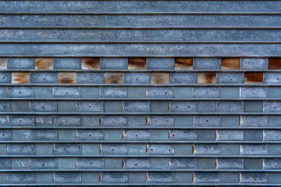
Corrugated metal gaskets form a multi-channel seal by pressing a stamped wavy metal core between flange faces, with each crest acting as an independent line-seal; flat metal gaskets produce only one or two contact lines and depend on plastic deformation of a uniform sheet [S1][S3].
The structural difference cascades into recovery behaviour: a corrugated gasket routinely shows elastic recovery above 90%, while a flat metal sheet under sustained bolt load creeps and loses seating stress after thermal cycling [S8]. Both types appear in the gasket family tree, but they sit at opposite ends of the resilience-versus-simplicity axis.
Sealing Mechanism: How Each Profile Converts Bolt Load Into Tightness
A flat metal gasket seals by plastic deformation: the sheet conforms to flange-face micro-roughness on first compression, then relies on residual gasket stress to hold the line. Once the bolt load relaxes, recovery is minimal, and the joint tolerates very little subsequent movement [S3][S8].
A corrugated gasket uses a different load path. The concentric V-, trapezoidal, or arc-shaped waves (each typically on the order of millimetres in pitch) concentrate line load at the crests, producing repeated parallel seal lines rather than a single plane. The valleys act as springs, and the metal-graphite facing fills the micro-channels between the flanges [S4][S7]. This multi-line behaviour is the defining advantage of the corrugated profile; it is also why corrugated cores are routinely laminated with flexible graphite or PTFE facings to seal the residual leakage paths [S2][S5].
Comparison: Corrugated vs Flat Metal Gasket Against Four Decision Criteria
On a side-by-side basis: (1) Sealing mechanism: corrugated = multiple parallel crest seal lines with spring-like valleys; flat = one contact plane with plastic deformation. (2) Elastic recovery: corrugated recovers above 90% after unloading; flat recovers only marginally and creeps under sustained load [S8]. (3) Cyclic service: corrugated tolerates thermal cycling and radial shear (e.g. heat-exchanger tube sheets); flat is recommended only for low-cycle or static joints [S2][S3]. (4) Manufacturable thickness and tolerance: photo-etched flat gaskets span 0.01–3.0 mm with ±0.03 mm tolerance; corrugated sheets must be thick enough to stamp a deep wave, so they sit at the upper end of metallic-gasket thickness ranges [S3].
Pressure capacity splits the two designs clearly. Flat metal gaskets are described as suitable for low-to-moderate-pressure systems, with temperature cycling able to loosen the seal over time [S3]. Corrugated cores in heat-exchanger service routinely take around 45 ksi gasket stress, provided bolt load is calculated per ASME PCC-1 Appendix O to avoid overstressing the corrugations [S2]. For high-pressure wellhead service, the comparison shifts to ring-joint designs, where BX rings exceed 20,000 PSI per API 6A, a regime neither corrugated nor flat sheets are designed for [S3].
Where Corrugated Wins, Where Flat Is the Right Call
Specify corrugated when the joint sees radial shear, thermal cycling, or fluctuating internal pressure. Heat-exchanger channels and expansion-joint flanges are the canonical applications, because the wave geometry absorbs differential movement while the graphite facing maintains line contact [S2][S4]. Corrugated cores are typically built from 304 stainless, 316 stainless, carbon steel, or higher-temperature alloys, with flexible-graphite facings dominating petrochemical service [S2][S5].
Flat metal gaskets remain the right call for low-to-moderate pressure enclosures, HVAC equipment, general machinery, and electronic or grounding interfaces where thickness under 3.0 mm and tight ±0.03 mm tolerances matter more than resilience [S3]. They also suit thin, custom-shaped geometries that are awkward to wind or stamp, including complex hole patterns, slots, and irregular outlines produced by photochemical etching without mechanical stress or burrs [S3]. For a deeper look at semi-metallic composite sealing, the sealing technology overview lays out where flat metal fits among compressed fibre, rubber, and metallic options.
Failure Modes and Operating Constraints
Flat metal gaskets fail through blow-out under over-pressure, loss of seating stress after thermal cycling, and inability to conform to a warped flange face, all of which are documented in the standard guide to flat-gasket limits [S3]. The shape of the failure is essentially a slow leak once the residual stress decays below the line-seal requirement.
Corrugated gaskets fail differently. Documented weaknesses include graphite blow-out during thermal cycling when the metal core cannot re-seat the soft facing, poor recovery compared with spiral-wound designs in standard ASME B16.5 pipe flanges, and the risk that the corrugations are over-compressed if bolt load is not checked against ASME PCC-1 Appendix O [S2]. Corrugated cores are therefore widely discouraged for standard ANSI pipe flanges, where spiral-wound or kammprofile gaskets retain better recovery [S2]. For material-level details on how alloy choice affects this resilience, the metal-material reference compares common gasket-grade alloys.
Standards, Sourcing, and Selection Signals
Design calculations on corrugated cores have been validated against finite-element fluid-structure coupling models, with one NiTi alloy study showing a leakage-rate prediction model with an average error of about 16.81% versus simulation; the same study confirms that leakage is positively correlated with internal pressure and sealing-surface roughness [S1]. For procurement, the practical signals to track are: (a) ASME B16.5 / ASME PCC-1 compliance for bolt load and gasket stress, (b) API 6A conformance for any high-pressure wellhead ring joint adjacent to the corrugated joint, and (c) facing-material compatibility (graphite vs PTFE) for the specific process fluid and temperature window [S2][S3].
The next verification step for a specifier is to confirm the gasket stress envelope against ASME PCC-1 Appendix O and the facing material's published temperature ceiling, then cross-check the supplier's recovery test data at the design bolt load. If the joint cycles more than a few hundred thermal excursions per year, move the comparison toward spiral-wound or kammprofile designs before locking in corrugated, because the documented blow-out mechanism on standard pipe flanges is the leading disqualifier [S2].
See also our earlier report, Self-Cleaning Filter Backwash: When Flow Stops and When It Doesn't.