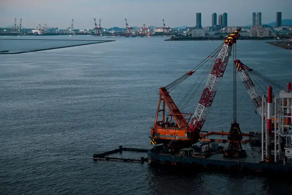
A crawler crane-mounted diaphragm wall grab is the flexible option, while a dedicated grab carrier is engineered for deeper excavation; Bauer's DHG-LT has a trench length of 2,800 mm and a trench width of 800–1,500 mm, while its DHG-V has a trench length of 2,400–3,800 mm and a trench width of 600–1,500 mm [S3].
The decision depends on trench width and depth, production rate, ground access, headroom, carrier availability and operating specialization, not simply rated lifting capacity. A dedicated carrier such as Bauer’s GB 80 S is specified to 80 m depth, whereas crawler-mounted grabs depend on the crane, boom, suspension and grab combination [S1][S3].
Carrier Choice by Depth, Width and Output
Hydraulic grabs suspend from a crawler carrier through hydraulic hoses, and their closing force is generated by a hydraulic thrust-rod system; this arrangement requires the carrier to provide compatible hydraulic power, stable working radius and controlled suspension [S2].
Bauer's DHG-V diaphragm wall grab has trench widths of 600–1,500 mm and trench lengths of 2,400–3,800 mm [S3]. Bauer DHG-LT equipment is listed at 800–1,500 mm trench width, 2,800 mm trench length and 2 × 450 kN cylinder force, while DHG-V covers 600–1,500 mm width, 2,400–3,800 mm length and 1,200 or 1,800 kN cylinder force [S2][S3].
A dedicated carrier gives the contractor a purpose-built system for excavation and slurry-wall production, while a crawler crane can support other lifting or attachment work between diaphragm-wall tasks. The trade-off is flexibility against specialization: a dedicated GB 50 carrier is approximately 17.3 m high and uses a 280 or 310 kW engine, while the GB 80 S is approximately 18.5 m high, has a 310 kW engine and is listed for 80 m depth [S3].
Crawler Crane Configuration and Operating Limits
Duty-cycle crawler cranes are used as carrier equipment for diaphragm wall grabs because they combine crawler mobility with controlled cable speed, sensitive braking and winch traction for trench excavation [S1]. A complete system must be checked as a crane, grab, suspension and support-fluid operation, rather than by selecting the grab from jaw width alone.
Reference SENNEBOGEN machines illustrate the carrier envelope: the 6140 HD is a 140 t duty-cycle crane with a diaphragm wall grab; the 630 E is listed at 30 t maximum load, 35.5 m hook height and diesel drive up to 186 kW; the 640 E is listed at 40 t maximum load and 41.1 m hook height [S1]. These are carrier examples, not universal limits for every diaphragm wall installation.
Hydraulic slurry wall grabs can be fitted with flexible guiding strips on the grab frame to help align the grab within the trench [S2]. For a crawler-mounted installation, also verify crawler-ground pressure, working-radius capacity, boom clearance, ground bearing capacity and site access. For crawler crane selection, the relevant duty cycle is repeated vertical handling of the suspended grab, not a one-off lift chart entry.
Dedicated Carrier Advantages and Constraints
A dedicated diaphragm wall carrier is the stronger choice when the work is dominated by deep trench excavation and the contractor can keep the machine assigned to diaphragm-wall duties [S3]. Purpose-built carrier packages integrate the grab, winch, hydraulic system and operating geometry, reducing the need to compromise around a general lifting crane.
Specialization does not remove siting constraints. The GB 50 has an approximate height of 17.3 m, and the GB 80 S reaches approximately 18.5 m [S3]. These dimensions make overhead clearance, access routes, slurry plant positions and support-fluid handling part of the equipment decision. The 80 m depth rating of the GB 80 S also requires confirmation of grab geometry, cable capacity, panel dimensions and the complete operating load at the specified radius.
A dedicated carrier is less attractive for a small contractor with intermittent wall work, multiple crane tasks or uncertain project volume, because the acquisition is specialized rather than broadly redeployable. Dedicated systems can still be rented or supported as coordinated grab-and-carrier packages, but the supplier should define responsibility for hydraulic supply, controls, winch function, measurement systems and maintenance.
Mechanical, Hydraulic and Rope-Suspended Grabs
Mechanical grabs use a two-rope arrangement, with the hoist rope and closing rope operating through multiple reeving over pulleys to increase closing force. Hydraulic grabs use cylinders driven through hoses from the carrier, and flexible guiding strips can be fitted to the frame to align the tool within the trench [S2].
Rope-suspended hydraulic grabs are also available for crane or dedicated-rig operation. CasaGrande identifies reduced vibration and noise relative to impact systems as advantages and identifies urban and infrastructure work as suitable applications [S4]. This arrangement does not remove the need to validate the carrier’s suspension, hydraulic supply and working-radius chart.
The comparison is straightforward: mechanical grabs favor rope-actuated simplicity and force multiplication through reeving; hydraulic grabs provide powered jaw control and optional guiding strips; rope-suspended hydraulic grabs can reduce transmitted impact effects. None should be accepted without matching jaw width, opening, trench length, closing force, depth and carrier geometry to the specified panel.
Where Each Configuration Performs Best
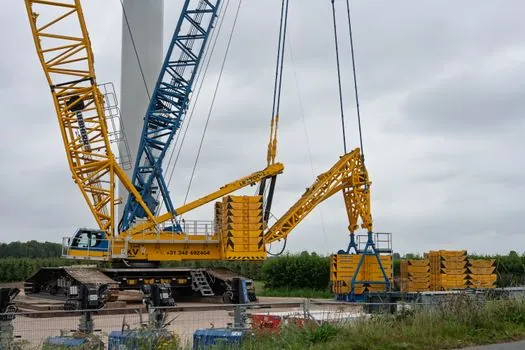
Choose a crawler crane-mounted grab for urban or infrastructure projects where mobility, compact access, phased trench construction and the ability to redeploy the carrier justify a flexible duty cycle crawler crane package. Liebherr identifies slurry-wall grabs for water-blocking walls around tunnels, open cuts and foundations, which covers cutoff, excavation-support and underground-structure applications [S2].
Choose a dedicated carrier for a high-volume wall package where the trench depth exceeds the practical operating envelope of available crawler cranes, low-headroom geometry rules out a general-purpose machine, or continuous diaphragm-wall production justifies dedicated controls and support equipment. A 70–80 m wall program cannot be accepted on a crane nameplate alone: the complete grab and suspension must be rated for that depth and working radius.
Use a mixed fleet only where workload genuinely supports it. Small or short panels can favor a crawler crane, while a deep, repetitive contract can favor a dedicated GB 80 S-type platform. The economic comparison must include mobilization, assembly, slurry plant, utilization, operator familiarity, maintenance ownership and the opportunity cost of leaving a crane unavailable for lifting work.
Procurement Checks for a Complete Wall System
Issue the carrier and grab as one performance-defined package. Require the supplier to state panel width, panel length, maximum operating depth, suspension type, grab mass, closing force, carrier configuration, working radius, cable or rope arrangement, hydraulic flow and pressure requirements, and available depth-measurement equipment. [S3]
For procurement, define the operating sequence around four controlled interfaces: excavation with support fluid, stop-end installation, reinforcement insertion, and tremie concreting while support fluid is displaced. The grab is only the excavation component; panel quality also depends on guide walls, trench stability, fluid management, reinforcement handling and concrete placement [S2].
Verify that the carrier has sensitive control and braking, satisfactory winch traction at high cable speeds, and hydraulic and electronic winch synchronization where specified. Bauer also offers optional measurement technology and assistance systems for diaphragm-wall grabs, so these should be treated as separately priced functions with defined outputs rather than assumed features [S1][S3].
Use dedicated carriers when depth and continuous output dominate, and use crawler crane-mounted grabs when access and redeployment dominate. The final selection should close with a manufacturer-confirmed load chart for the actual boom, grab, suspension, radius and depth, plus a site plan proving ground bearing capacity, guide-wall clearance and slurry-plant access.