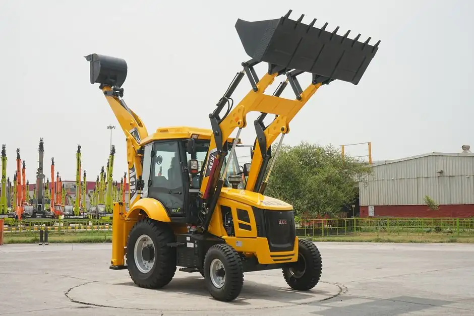
A diaphragm wall grab's nominal capacity should be checked against excavated volume per panel, while panel production depends on bite geometry, trench depth, soil resistance, crane cycle time, and slurry desanding capacity.
The comparison applies to hydraulic diaphragm wall grabs used for panel excavation in slurry-supported trenches; it does not cover continuous cutter production, and published equipment data provide geometry rather than a universal grab-to-output conversion.
Capacity versus panel excavation rate
Grab capacity and panel excavation rate are different quantities: capacity describes the tool's permitted working envelope, while production rate is completed trench volume per elapsed working time. The open trench is supported with slurry, which prevents groundwater from penetrating and the existing soil from subsequently breaking, and a trench cutter loosens the existing material and mixes it with the slurry for upward transport by a mud pump [S2].
Dividing that volume by the effective cycle time gives the required excavation rate, but the calculation must reserve nonproductive time for slurry cleaning, guide-wall alignment, panel completion, reinforcement-cage installation, and tremie concreting [S3].
Published examples show why no single output figure can be assigned to a grab size. A 0.6–1.1 m wall thickness and 2.5–6 m panel widths are cited for diaphragm walls, while panel dimensions and bite lengths depend on ground conditions, wall depth, structural position, and excavation equipment [S4].
Calculate the rate from volume and time
The governing production model is panel excavation rate equal to panel volume divided by excavation and support-cycle time. For example, a 1.0 m wide trench, 6.5 m long and 12 m deep contains 78 m³ before overbreak. At an effective excavation duration of 30 minutes, the required gross excavation rate is 2.6 m³/min; at 45 minutes, it is 1.73 m³/min. These values are calculated examples, not manufacturer performance claims. [S3]
Use separate time allowances for soil loosening, bucket withdrawal, slurry-slot filling, vertical positioning, and interruptions. The DHG method uses a diaphragm wall grab, and the material loosened by the cutting wheels is mixed with the slurry and transported upward by a mud pump [S2]. If desanding cannot process the solids load, the apparent grab cycle cannot be sustained even when the machine has ample hydraulic capacity.
Confirm all assumptions against the proposed panel schedule. A grab with a nominal bucket volume of 1.5 m³ does not establish 1.5 m³ per cycle; fill factor, loosened-soil swell, trench width, bite depth, and the fraction of each pass recovered as solids all affect the effective contribution to panel completion.
Equipment and trench geometry
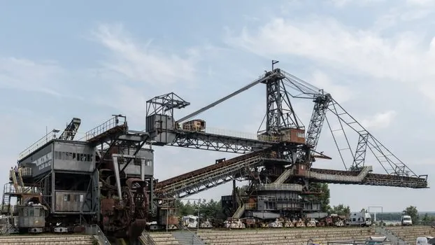
Panel depth can range from 10–75 m depending on the crawler crane [S7]. These limits define feasible applications, but they are not equivalent to uniform production across that range.
Selection should follow four criteria. First, match grab width to required panel width rather than maximizing bucket volume. Second, verify maximum reach and trench depth against the carrier configuration. Third, establish required operating weight and lifting capacity from the installed grab, soil-filled bucket, and crane configuration. Fourth, require enough working headroom because diaphragm-wall equipment needs more space than conventional excavation methods [S3].
The diaphragm wall grab is suitable for conventional panel excavation and bounded trench depths, while a trench cutter is generally the stronger option for hard or very hard ground and deep trenches because cutting wheels loosen the material and slurry transports it upward [S2].
Soil and slurry constraints
Soil resistance changes the grab's effective work more than its catalog capacity does. Trench cutters are especially used in hard or very hard soil conditions and at large trench depths [S2].
Slurry performance is equally critical. Bentonite slurry is used to limit local trench collapse, guide walls preserve horizontal alignment, and the guide wall assists vertical positioning of the grab [S3][S4].
The practical constraint is the weaker link: crane cycle, grab penetration, slurry desanding, or reinforcement handling. A nominal grab capacity above the required daily output offers no schedule benefit if slurry treatment or crane handling sets the lower rate.
Compare grab and cutter choices
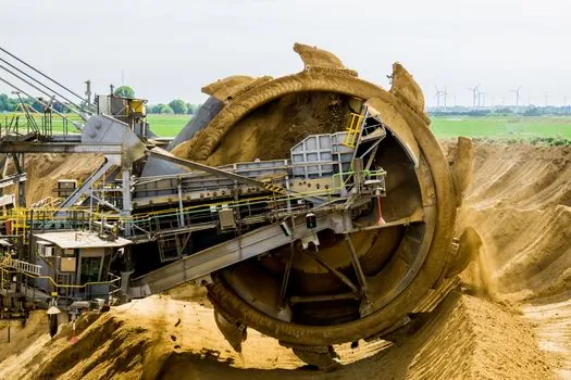
For the comparison decision, a diaphragm wall grab provides discrete excavation cycles, is suited to soils where penetration remains practical, and uses trench widths of up to 1,500 mm in BAUER's DHG V specification [S2]. A trench cutter supports large trench depths and hard or very hard soil, but its production depends on cutter design, slurry pumping, and desanding rather than a comparable published bucket-volume figure [S2].
A hydraulic dynamic compactor is not a substitute excavation tool, although compaction equipment may be used elsewhere in foundation work. For this decision, the relevant comparison is the diaphragm wall grab versus the slurry-supported trench cutter, with criteria covering soil hardness, trench depth, operating cycle, and slurry treatment. The selection variable should be required panel volume per shift, not grab catalogue capacity alone.
For normal soils and manageable trench depths, specify the grab for proven panel geometry and cycle control. Shift to a cutter when depth or hardness moves beyond the grab's practical operating range. Soil Mec's 10–75 m panel-depth range identifies a broad system capability, while BAUER records cutter depths exceeding 250 m; these are achieved application records, not guaranteed production ratings [S2][S7].
Operating controls and procurement checks
Procurement acceptance should include measured trench width, maximum excavation depth, bucket volume, operating weight, carrier compatibility, and required cycle time. The supplier should state which values are geometric limits and which are production expectations under defined soil conditions. A 3,800 mm trench length and 1,500 mm trench width are maximum dimensions in the cited DHG V data, not guaranteed output at every depth [S2].
Measure field performance over complete panel cycles, including slurry solids concentration and desanding time. Track excavation minutes, volume removed, bucket passes, panel width, depth, soil condition, crane utilization, and delays. Compare actual panel volume per working hour with the planned production rate, then adjust the schedule or equipment rather than assuming additional bucket capacity will recover the deficit.
For a 6.5–8.0 m panel formed from multiple bites, the project team should record each bite separately because side and middle bites have different lengths and may not have equal durations [S3][S4]. A comparable carrier-selection issue is covered in Crawler Crane vs Dedicated Diaphragm Wall Carrier.
Primary panels and T-panel interfaces
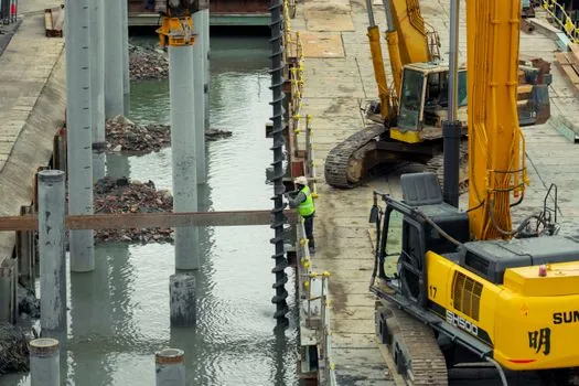
Primary panels are excavated before adjoining panels, and their minimum length depends on grab size, generally being of the order of 3.0 m [S3]. Stable ground permits multiple-bite construction, with the left and right portions excavated before the middle bite; panels of approximately 6.5–8.0 m can be achieved by this sequence [S3].
T-panel, corner-panel, joint, and reinforcement operations can therefore interrupt nominal excavation output. Joint selection depends partly on the excavation equipment, with flat, circular, steel-beam, and grooved water-stop configurations documented; grooved joints with water stops are commonly preferred, while steel I-beams are also used in the United States [S3]. The pile driver is not part of the normal grab production cycle, but comparable deep-foundation planning should separate equipment installation from repetitive excavation duties.
The next trackable signals are measured m³ per panel cycle and slurry-plant throughput. Require the field team to submit both before accepting a production guarantee, then compare the measured pair against the excavation schedule and the selected grab's width and operating limits.