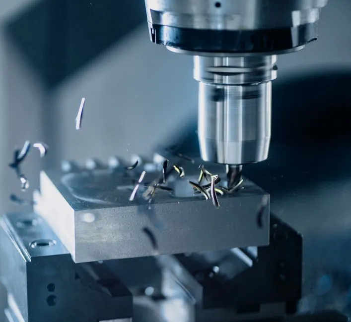
A cut-off machine vise can hold round bar, but clamping force alone will not secure it: the workpiece must also have flat seating surfaces, adequate jaw engagement, and enough resistance to the cutting force.
The workable approach is to flatten or locate the round stock, keep material in the jaws, reduce cutting aggressiveness when clamping only on the diameter, and verify that the workpiece cannot rotate or lift under the load [S1].
Clamping Force and the Force on the Workpiece
For a 6-inch machinist vise, 150–200 ft-lb of handle torque can produce approximately 5,000–15,000 lbf of clamping force [S4]. This available force is not the same as the force the workpiece can tolerate. A round bar can rock, lift, or receive an indentation even when the vise is tightened beyond its useful range.
Clamping force must exceed the resultant cutting force multiplied by a safety factor. That is a starting point for the calculation, not permission to use 375 lbf on every round bar. Contact geometry, workpiece height, leverage, and the tendency of round stock to roll under the cutter can make the actual demand higher.
The vise itself has limits. A 0.125-inch-per-revolution leadscrew with a stated efficiency of 0.25–0.40 converts applied handle torque into axial clamp force, so doubling handle torque does not necessarily double useful grip if friction, screw condition, or jaw geometry is unfavorable [S4]. Use the force value only after confirming that the workpiece is seated, the jaws are parallel, and the handle does not bottom the screw.
Flat Contact, Centerlines, and Round-Bar Geometry
Two flat jaw walls gripping a cylinder do not create a geometrically stable location unless the part has been prepared to seat against both jaws. For short jobs, flattening the future reference face and seating the piece against a parallel can verify that it is not inclined or rocking [S1]. A dead-blow tap can settle the piece before the jaws are fully tightened.
A 10-degree taper on the workpiece was proposed as one method for reducing the tendency of a 1-1/2-inch-diameter, 2-inch-long 4140 PH bar at 30 HRC to lift during a facing cut [S1]. That arrangement is not a universal clamping specification. Tapered workholding can improve contact against a cylindrical surface, but it changes the required geometry and leaves less stock available for machining if the taper is created as part of the production process.
For larger or longer round parts, locating features are often more reliable than friction alone. That approach is suited to repeatable production, where the locator can be matched to the stock and the same geometry can be used from setup to setup.
Grip Depth Sets the Practical Limit
A practical baseline for general milling work is 0.100 inch of jaw engagement, with 0.250 inch preferred for many applications; 0.250–0.750 inch is described as a more comfortable range for general-purpose work [S5]. These are machining-practice values rather than a formal vise rating. The key constraint is that reducing grip depth must also reduce cut forces and tool pressure.
Thin workpieces expose the inverse relationship between pressure and contact area. At a 5,000 lbf clamp force, the calculated contact pressure is 12,500 psi at 0.100 inch of engagement on a 4-inch-wide face, 10,000 psi at 0.125 inch, 5,000 psi at 0.250 inch, and 2,500 psi at 0.500 inch [S4].
For very thin stock, glue or tape to a rigid substrate, a soft jaw, or a dedicated hold-down can preserve flatness more effectively than squeezing the part between hard jaws [S5]. For round stock, the same principle applies: a short, precise locating contact can resist rotation better than a shallow but poorly located grip.
Comparing the Main Clamping Methods
Hard-jaw diameter clamping offers the shortest setup and works for low-volume cuts, but it depends on friction, can mark the cylinder, and may allow roll or lift. Cutting on the diameter requires less aggressive tool engagement [S1]. It is a practical choice for occasional trimming, not the best method for heavy or repetitive production.
Prepared flats and a parallel provide a more definite seat and allow the machinist to check whether the part is inclined [S1]. The cost is the preparation of two surfaces and the loss of some usable stock. This method suits short or moderate jobs where milling two flats is practical.
The proposed 10-degree taper on the workpiece is intended to help keep the part from pulling up. This approach requires controlled jaw preparation and accurate alignment.
It adds fixture cost and setup time, so it is not justified for a one-off cut unless the machine, bar diameter, and production volume justify a dedicated locator.
Where Round-Stock Clamping Fails
Roll is the first failure mode. A cylinder can rotate around its axis under cutter torque, especially when only the curved surface contacts both jaws. The remedy is a flat, a notch, a V-jaw profile, a taper, or another positive locator. Tighter handle torque does not eliminate this geometric movement. [S4]
Lift is the second failure mode. The workpiece can lever out when cutting force acts above the jaw line, and tall parts create a larger overturning moment [S4]. Keeping the cut below or near the jaw line reduces leverage. Moving the workpiece toward the fixed jaw and modifying the fixed jaw for a production run were proposed controls for lifting in the 4140 bar example [S1].
Distortion and marking form the third failure mode. Serrated hard jaws concentrate pressure on small features, while insufficient engagement raises local pressure [S4]. Aluminum jaws were reported to provide roughly five times the grip of steel-to-steel contact in one machining discussion [S1], but that ratio is a forum observation rather than a controlled test. Soft or serrated jaws also leave marks and require adequate depth to bite consistently.
Choosing the Method by Production Demand
For one-off or low-volume trimming, use the vise's flat jaws with a prepared flat or a checked parallel, then reduce the cut when the round surface provides limited purchase [S1]. For tens of thousands of identical parts, modifying the fixed jaw or installing a profiled soft jaw is more defensible than repeating a hand-tapered setup [S1].
For automated or high-force production, use a round-part locator with a defined clamping depth. The 3 mm engagement published for one round-part clamping system provides a concrete design target, but the locator must still be matched to the actual diameter and machining geometry [S3].
Record the jaw engagement, clamp force, workpiece height, cutter size, and cut strategy for repeat setups. Verify that the chuck or vise area has enough backing force for the machine and operation. A secure round workpiece should resist both the downward cutting load and the rotational component of cutter torque without relying on the operator to discover movement during the cut.