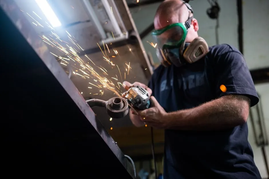
A 4.5-inch (115 mm) abrasive cut-off wheel is commonly rated for 13,300 RPM, corresponding to an 80 m/s peripheral speed [S7].
The wheel diameter, maximum RPM label, grinder speed, arbor size, guard, and machine rating must agree before the wheel is mounted on a cut-off machine or angle grinder.
Read The Wheel RPM Label Before Matching The Grinder
The wheel label is the controlling speed reference: its marked “Maximum RPM” must equal or exceed the grinder spindle RPM [S1]. A typical 4.5-inch wheel carries a 13,300 RPM maximum [S3], while a documented 6 x 0.040 x 7/8-inch fiberglass-reinforced wheel is rated at 10,200 RPM [S5].
Wheel speed is not interchangeable with tool speed alone. A 4-inch wheel marked for 10,000 RPM must not be run on a grinder producing 12,000 RPM, because overspeed raises the risk of wheel failure [S6]. Do not infer the permitted speed from diameter or from the fact that the wheel physically fits.
The machine’s no-load spindle speed can differ from its operating speed after load is applied. Verification should therefore cover the actual grinder setting, spindle or variable-frequency drive control, and the wheel label rather than relying on a nominal motor speed.
Compare Wheel Size Against Rated RPM
For a 4.5-inch (115 mm) cut-off wheel, the common 13,300 RPM rating corresponds to 80 m/s peripheral speed [S7]. A 6 x 0.040 x 7/8-inch wheel listed at 10,200 RPM is fiberglass-reinforced and intended for steel, iron, and other ferrous metals [S5]. These examples show why identical-looking grinders can require different wheels.
Arbor size is a separate compatibility check. The documented 6-inch wheel has a 7/8-inch bore, while its listed dimensions are 6-inch diameter and 0.040-inch thickness [S5]. A wheel with the correct RPM rating can still be unusable if the bore does not match the spindle flange and the manufacturer’s mounting arrangement.
Choose The Wheel Shape For The Cutting Geometry

Type 1, also identified as Type 41, is a flat cut-off wheel with more available cutting surface and less interference with the workpiece; it suits deep 90-degree cuts in grinders, die grinders, high-speed saws, stationary saws, and chop saws [S1]. Type 27, also identified as Type 42, has a depressed center that improves visibility and supports flush cutting, but it has less ability to cut tightly around corners, profiles, and extrusions [S1].
Type 1 cutting wheels, also known as Type 41 cutting wheels, are completely flat. The cutting machine type therefore matters as much as the wheel diameter when the intended cut includes a flush side or a constrained working angle.
A cutting wheel is not a general-purpose grinding wheel. Cutting wheels make narrow cuts at approximately 90 degrees and are generally thinner than grinding wheels; they lack the lateral strength needed for side grinding [S1]. Using a thin cut-off wheel for side loading can therefore create an avoidable failure mode, independent of whether its RPM label is satisfied.
Match Abrasive Grain And Wheel Construction To The Workpiece
The workpiece should therefore drive the abrasive specification after the RPM and mounting checks are complete.
Fiberglass reinforcement improves wheel integrity, and a documented 6-inch wheel uses high-tensile fiberglass mesh within its bonded abrasive construction [S5]. That wheel is rated to ANSI B7.1 and specified at 10,200 RPM, 6-inch diameter, 0.040-inch thickness, and 7/8-inch bore [S5]. These four data points should travel together in a purchase record because changing diameter, thickness, or bore can invalidate a convenient substitution.
Cutting technique also changes wheel loading. Scoring a casting differs from plunging into it, and excessive plunge pressure may shorten wheel life [S4].
Apply Hard Limits For Production Cut-Off Machines
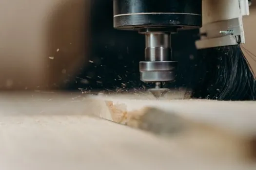
Production selection should reject any wheel whose marked RPM is below the spindle’s permitted speed. This is not an area for operator discretion or a 10% informal margin: an 8-inch wheel marked 3,105 RPM was found unsuitable for a spindle operating at 3,600 RPM even though the wheel physically fitted the machine [S2].
The same case illustrates why speed control belongs in the machine specification. One possible solution for safer use of larger wheels is a variable-frequency drive, although its practicality depends on how reliably users select the operating speed based on wheel size. For procurement, a cut-off machine specification should state the maximum wheel diameter, minimum and maximum spindle RPM, wheel bore, guard coverage, and required wheel certification.
A shop should inspect each wheel for cracks, edge damage, contamination, and label legibility before installation, then quarantine any wheel without a readable RPM or dimensional specification. The wheel should never be run beyond its marked maximum, and changing the spindle control system should not be treated as permission to exceed the wheel label [S1][S6].
Verify The Complete Compatibility Chain
A traceable selection record should contain five items: wheel diameter in inches or millimetres, maximum RPM, thickness, bore size, and reinforcement or safety marking. The documented 6-inch example, for instance, is 6 x 0.040 x 7/8 inches and 10,200 RPM [S5], while the common 115 mm example is 13,300 RPM at 80 m/s [S7].
Do not confuse wheel RPM with spindle horsepower, feed rate, or material removal rate. A fast spindle does not make a slower-rated wheel acceptable, and reducing feed cannot make an overspeed installation compliant. Confirm the grinder model, wheel type, RPM label, bore, guard, and workpiece before adding an abrasive wheel to the work-control plan.
Track two procurement signals for each cut-off cell: the wheel label maximum compared with the machine’s maximum spindle speed, and any replacement-wheel request that changes diameter, bore, or reinforcement. Record the selected wheel’s 4.5-inch/115 mm and 13,300 RPM rating or 6-inch/10,200 RPM rating with the work instruction so the same safe pairing can be reproduced during maintenance.