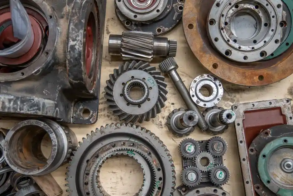
A cycloidal reducer for a steel mill must be engineered around three realities: continuous high torque, ambient heat near 60-80°C around reheat furnaces, and shock transients from mill stands, coilers, and reversing tables. Multi-tooth pinwheel engagement lets these units absorb impact loads that destroy thin-walled flexspline (harmonic) cups, with documented torque density 2-3x higher than comparable flexspline designs [S2].
Steel mills run cooling bed conveyors, screw conveyors for slag and sinter, ladle transfer cars, coiler mandrels, and roller table drives, all of which impose different load spectra on a single reducer family. The same planocentric principle serves each, but the sizing math, lubrication, and sealing strategy diverge sharply between a coiler mandrel and a sinter cooler screw [S4].
Why Cycloidal Geometry Survives Steel Mill Shock Loads
Planocentric (cycloidal pinwheel) reducers transmit torque through multiple teeth engaged simultaneously between a lobed cycloidal disc and a fixed ring of output pins, distributing load across multiple contact points rather than relying on a single tooth pair [S4]. On a reversing coiler mandrel, where peak torque can hit 200-300% of running torque during a coil build-up, this multi-tooth contact prevents the tooth-skip failure mode that flexspline thin-walled cups exhibit under the same transient [S2].
Rolling element contact (the eccentric bearing riding inside the cycloidal disc) replaces the gear-mesh sliding friction of a planetary stage, which is the source of the inherent backlash in planetary reducers [S2]. For a screw conveyor under slag or sinter load, this rolling contact also lowers input inertia, reducing the inrush current spike on every start across a 24/7 rolling mill duty cycle [S4].
Selection Criteria: Reduction Ratio, Service Factor, Thermal Class
Three specifications must be locked before any vendor quote: reduction ratio, mechanical service factor, and thermal rating at the installed ambient. Material handling guidance (June 2026) lists torque, output speed, reduction ratio, and duty cycle as the four primary checks; for steel mills the duty cycle is rarely below 16 hours/day and often 24/7, so the service factor must be applied to the running torque, not the nameplate motor torque [S4].
Reduction ratios for a single-stage cycloidal unit commonly span 11:1 to 119:1, and two-stage stacks reach 121:1 to 7569:1, which lets a 1450 rpm 4-pole motor drive a coiler mandrel down to roughly 1-2 rpm without an external gearbox [S1]. Lubricant grade must be re-selected for the 60-80°C ambient near reheat furnaces; standard mineral oil at ISO VG 320 may need replacement with synthetic PAO or a higher VG to keep the oil film above 0.5 cSt at sump temperature.
Steel Mill Application Map: Where Cycloidal Wins and Where It Loses
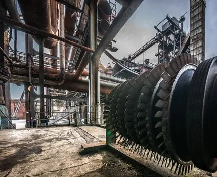
Use a cycloidal reducer where the load profile is shock-heavy, the output speed is low, and the installation envelope is tight: coiler mandrels, roller table drives, screw conveyors under sinter or slag, ladle transfer car traction, and walking beam conveyors all fit this profile [S3][S4]. The same planocentric architecture also serves cooling bed transfers, where the multi-tooth contact smooths torque ripple that would otherwise shake product identification tags off hot billets.
Avoid specifying a cycloidal reducer where continuous high-speed operation above 1800 rpm input is required, where the ambient exceeds the seal rating without active cooling, or where AGMA Class I or II precision is demanded at less than 1 arc-min backlash (a precision strain wave unit is the better match at sub-arc-min accuracies) [S2]. On a sinter cooler main drive, verify that the output bearing can carry the radial load from the screw flight; cycloidal bearings are sized for torque, not always for overhung load, and a separate outboard bearing may be required.
Material and Heat Treatment for Mill Ambient Conditions
Common cycloidal disc and pin materials include 20CrMnTi and 18CrNiMo7-6 alloy steels, case-hardened to HRC 58-62, which gives the wear resistance needed for 40,000+ hour operating life under mill dust ingress [S5]. Cast iron housings are acceptable for screw conveyor duty where vibration damping matters, but ductile iron is the better pick for any drive that sees reversing torque, such as a coiler or a screw conveyor that runs forward and reverse for cleaning.
Sealing is the dominant failure mode in steel mills, not gear wear. Mill dust, scale, and water from descaling sprays defeat standard lip seals; specify IP65 input seals, fluorocarbon (FKM) output seals rated to 120°C, and a breather pre-filtered with a desiccant for any reducer mounted within 5 m of a descaling header. For comparison, an underground mining conveyor faces similar dust but no heat; the cycloidal reducer selection guide for mining shock loads covers the shock side, but the thermal side here is unique to hot strip and reheat environments.
Comparison: Cycloidal vs Harmonic vs Planetary for Mill Service

On four decision criteria relevant to a hot strip mill, a single-stage cycloidal unit rated for the same input power outperforms harmonic (strain wave) and planetary units in three of four: torque density is 2-3x higher than a flexspline of similar size, shock load tolerance is materially better than the thin-walled flexspline cup, and overhung load capacity is higher than an equivalently sized planetary stage [S2]. Backlash and kinematic accuracy are where the harmonic drive still wins, reaching sub-arc-minute; a cycloidal achieves true zero backlash at the rolling contact but typical AGMA precision grades are 1-3 arc-min, fine for a coiler but not for a position-controlled screwdown [S2].
For a holistic look at the cycloidal architecture beyond mining, the encyclopedia entry on cycloidal reducers covers the geometry and ratios, while the planetary reducer reference documents the meshing-gap-driven backlash that a cycloidal design avoids. The RV reducer encyclopedia page is the right cross-reference if the application is a high-tilting-moment roller table where the second stage of an RV cycloid hybrid adds the needed moment stiffness.
Verification Tests Before Acceptance
Run no-load back-to-back at 1.5x rated input speed for 4 hours and record temperature rise: a healthy cycloidal unit stabilises below 70°C above ambient on mineral oil, below 60°C on synthetic, and the reading must be taken at the sump, not the housing, since the housing runs 5-10°C cooler [S4]. Apply a stall test at 2x rated output torque for 30 seconds; any permanent deformation of the cycloidal disc profile under this overload indicates the case-hardening depth was underspec for the mill's actual service factor.
Vibration acceptance follows ISO 10816-3 Class 2 for the input coupling; on a mill where a 1450 rpm motor runs through a 30:1 cycloid, the output side at 48 rpm falls into ISO 10816-3 Class 4 severity limits, so velocity RMS above 4.5 mm/s on the output bearing housing flags bearing or pin-gear wear before the next planned outage.
Trackable signals for the next procurement cycle: (1) the OEM's published thermal rating curve at 80°C ambient with synthetic PAO, and (2) the documented service factor at 100% duty versus the conservative nameplate figure. Either parameter trending downward across vendor datasheets in 2026 indicates rising competition, not quality loss, and is a lever for renegotiation on the next rolling mill overhaul contract.