
A cyclonic inlet device is the first internal inside an oil and gas separator vessel, sitting on the inlet nozzle and turning a high-momentum two-phase feed into a controlled, swirling distribution before the bulk disengagement section [S1][S3]. At design conditions the centrifugal acceleration imparted on individual droplets or particles can reach several hundred times the acceleration due to gravity, which is why cyclonic inlets can replace much larger gravity-settling sections in the same service [S1].
The article covers the operating envelope, the three dominant geometries (tangential-tube, vane-pack, and bi-vane), the pressure-drop/liquid-level trade-off, the limits where a cyclonic inlet stops being the right answer, and the standards/specification context a process engineer needs to write a defensible datasheet. The cyclone separator family is treated in detail in the encyclopedia entry; this piece focuses on the inlet device as a sub-component of that family.
Operating principle and why it replaces a large gravity section
Process fluid enters a manifold and is directed through a tangential opening into a vertical tube, which imparts a centripetal acceleration that drives the denser liquid and solid phases to the tube wall while gas migrates to the central axis [S1]. Because droplet migration is governed by centrifugal force rather than buoyancy, residence time and vessel diameter drop sharply for a given cut size, and one cyclonic inlet device can do the work of a long gravity-settling zone in a much shorter vessel [S1][S4].
The acceleration scale, "several hundred g" at design point, is the headline number a datasheet should anchor on, because the achievable liquid-removal efficiency at the inlet scales with it [S1]. The same swirl field that strips bulk liquid at the inlet also breaks the incoming jet, so foam formation downstream of the nozzle is reduced when the device is correctly specified [S1]. Note that the same high-g field that aids separation also imposes a meaningful pressure drop, which is the central trade-off a designer has to manage [S5].
Three dominant geometries: tangential-tube, vane-pack, bi-vane
Tangential-tube designs (e.g. ALTA-Cyclone Vortex Tube, VORSOMAX cyclonic inlet device) use a manifold of cylindrical tubes with a tangential entry at the top of each tube; the flow is distributed to each tube through a common header engineered for even split, and the assembly is welded or flanged to the inlet nozzle [S1][S2]. A retrofit option is available where welding to the vessel wall is not possible, which matters for live-vessel retrofits on operating platforms and refineries [S1].
Vane-pack designs (e.g. side-entry vane inlet device) are typically axial and use a stationary vane bundle to impart swirl to the whole stream in one pass, with the device rated from gas-dominated to liquid-dominated flows in a single hardware line [S7]. Bi-vane distributors split the inlet stream into two equal streams and deflect each through 90 degrees, producing a centrifugal gas/liquid separation effect at lower momentum than a full tangential cyclone, which is the common choice for low-momentum services [S3].
Comparison on the four criteria a datasheet usually scores against: (a) flow regime coverage, (b) pressure drop per stage, (c) tolerance to fouling/solids, (d) vessel-orientation flexibility. Tangential-tube handles gas- or liquid-dominant flow in vertical or horizontal vessels, with moderate-to-high ΔP and good solids tolerance because each tube is a discrete flow path [S1]. Vane-pack spans the widest gas-to-liquid ratio range in a single device, has the lowest ΔP, and is the most fouling-tolerant because there are no small tangential entries to plug [S7]. Bi-vane is the lowest-momentum option and is preferred where the feed is already near design velocity and any added ΔP is unacceptable [S3].
Pressure drop, liquid level, and the system-level trade-off
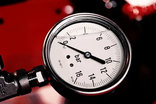
Pressure drop is the single most important number on a cyclonic inlet datasheet, because it directly moves the operating liquid level in the downstream vessel [S5]. Mesh pads, vane eliminators, and inlet vane diffusers impose relatively low pressure drop and have a small effect on liquid level; inlet cyclones and demisting cyclones, by contrast, carry meaningful pressure loss and therefore shift the separator's internal liquid level, which in turn affects degassing, level control, liquid/liquid separation, and surge control [S5].
A practical rule: a higher inlet-cyclone ΔP buys a smaller vessel at the cost of tighter level-control margins downstream, and a vane-pack or bi-vane buys back level-control margin at the cost of a larger vessel or a coarser inlet cut [S5][S3]. For feed streams with high GOR, high momentum, or risk of foam, the higher ΔP of a tangential-tube device is normally accepted because the foam suppression and bulk-liquid removal outweigh the level-control penalty [S1][S5]. For low-GOR, near-atmospheric, or level-control-sensitive services, a vane-pack or bi-vane is the safer call [S3][S7].
Where a cyclonic inlet is the wrong answer
Cyclonic separators, including the inlet device, operate well in fouling service because they have no small-mesh pads or fine passages, and they process high flow capacities and high liquid loadings, which is why they are among the most compact separation options [S4]. They are the wrong internal, however, when the service is genuinely sub-atmospheric with very low differential pressure available, because the swirl field requires a non-trivial ΔP to develop, and the device will starve the downstream section of gas if the system pressure is already marginal [S4][S5].
They are also a poor fit where the feed is already a slow, dispersed mist that does not need momentum destruction, because the swirl field will re-entrain fines downstream of the device rather than capture them. In those services, a lamps and light fittings-style upstream calm section plus a downstream mist eliminator pad is a more efficient train than a cyclonic inlet feeding a demister. A third failure mode is over-speccing a tangential-tube device on a low-GOR crude service: the high-g field will generate fine secondary droplets that the downstream demister then has to catch, negating the inlet device's bulk-removal benefit [S5].
Standards, sourcing, and datasheet signals to track

Cyclonic inlet devices are typically specified under the same vessel-internal package as mist eliminators and vane internals, and the engineering deliverable is usually a vendor selection report plus a pressure-drop / separation-efficiency guarantee tied to a defined feed composition and operating window [S2][S5]. Patent literature on this hardware class (e.g. US10792592B2, an inlet device with cylindrical separation cans for phase separation) is the most reliable public record of the canonical geometries and their internal layouts [S6].
Trackable signals a process engineer can follow: (1) the vendor-published ΔP vs inlet-velocity curve at the design GOR, which sets the level-control margin in the downstream vessel [S5]; (2) the vendor's stated tolerance to solids and fouling, since a tangential-tube design with many small tangential entries is more plugging-sensitive than a single-pass vane-pack [S1][S7]; (3) whether the device is offered in a flanged, weldable, or clamp-style mount, which determines whether it can be retrofitted into a live vessel without hot-work [S1]. These three data points, together with the construction machinery and equipment class of the host vessel, are the inputs a specifier needs before a self-cleaning filter backwash decision can be made on the downstream liquid train.