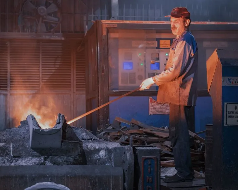
A vertical cylindrical shell is the dominant steel-mill geometry because its 20 to 100 mm steel wall plus layered refractory lining keeps shell-side heat flux low, and the open top is sealed with a refractory lid for pouring ladles serving BOF, EAF and LF routes [S1][S2].
Conical shells (narrower at the bottom, wider at the slag line) are still specified where skull removal, lip pour ergonomics, or reduced vortexing during bottom-pour teeming are priorities, at the cost of higher refractory hot-face exposure [S1][S5].
Geometry Definition and Where Each Shape Is Used
A modern steel ladle is an open-topped vertical vessel with a heavy steel shell 20 to 100 mm thick and a layered refractory lining up to 400 mm thick, used to transfer molten metal between furnace, ladle furnace (LF), and continuous caster [S1]. The shell itself can be cylindrical, slightly conical, or barrel-shaped, and the ladle sits on a transfer car or is lifted by overhead crane with capacities exceeding 300 tonnes for BOS hot-metal charging [S1][S4].
Cylindrical shells are standard in continuous casting because the uniform cross-section simplifies thermal modelling and refractory installation. Conical shells (narrow bottom, wider top) are preferred for high-purity metal and die-casting tilting-ladle applications where non-cylindrical inner profiles require closed-surface flux calculations to predict pour rate [S3][S5].
Heat Loss Comparison: Cylindrical vs Conical
Cylindrical ladles lose heat mainly through the exposed slag surface, the refractory lining, the steel shell by radiation and convection, and the bottom block, with the top (lid or open bath) accounting for the single largest share of the budget during holding [S2][S6]. A typical operating bath in a well-insulated cylindrical ladle drops 0.5 to 1.0 degrees C per minute during transfer; uninsulated or conical thin-bottom designs can run 1.5 to 2.0 degrees C per minute because the smaller bottom footprint concentrates conductive loss [S2].
Conical shells, with their reduced bottom diameter, expose less refractory surface area to the bath at the pour zone but concentrate heat flux per unit area, which can drive shell hot spots near the cone-to-barrel transition [S1][S5]. Cylindrical shells distribute the flux more evenly along the barrel, allowing calcium silicate backup boards to be installed as a uniform 50 to 75 mm insulation layer between the permanent lining and the steel shell, dropping shell-side temperature by roughly 80 to 120 degrees C in published case studies [S2].
Pouring Control and Flow Rate Behaviour
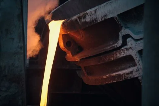
Bottom-pour ladles use a slide-gate or stopper-rod nozzle to control flow, while lip-pour designs rely on the tilt angle and bath hydrostatic head, with conical inner surfaces needing angular velocity compensation to maintain constant flow rate [S3][S5]. The Wang 2026 study on non-cylindrical inner surfaces used the Gauss divergence theorem to derive piecewise angular velocity functions, showing that variable tilt-velocity profiles (high initial, reduced once metal exits the spout) suppress surface fluctuation, air entrapment, and oxide film inclusions during high-pressure die casting [S3].
For very large hot-metal ladles exceeding 300 tonnes, the digital twin work by Popov (2024) ties pour rate to the rate of change of bath height and surface area, an approach that works equally well for cylindrical and mildly conical shells because the geometric term is computed from the live bath level, not a fixed cross-section [S4].
Selection Criteria: When to Pick Cylindrical, When to Pick Conical
For steel-mill transfer, LF refining, and continuous casting tundish charging, specify a cylindrical shell with high-density calcium silicate backup insulation, a refractory lid, and slide-gate bottom pour; this combination minimises total heat loss, gives the most uniform shell temperature, and supports the simplest automatic pouring control [S1][S2][S5].
For foundry die-casting and high-purity metal smelting where intermittent tilting pour is the operating mode, choose a conical inner profile; the non-cylindrical shape is intentional and must be paired with a closed-surface flux model and a variable angular velocity controller to hold constant mass flow rate across the tilt arc [S3].
Failure Modes and Operating Constraints
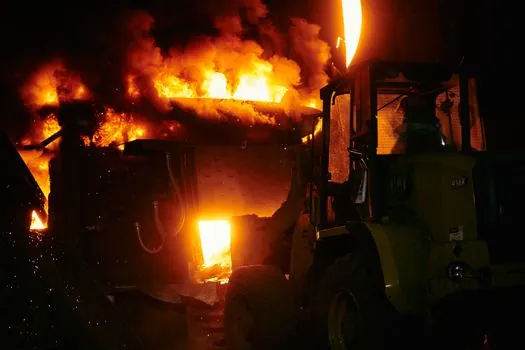
Excessive heat transfer through the lining pushes shell temperature into the red-hot range, raising stress and risking emergency inspection or shortened ladle campaign life; the most common trigger is loss of the backup insulation layer rather than working-lining wear [S2]. A second failure mode is thermal spalling when cold ladles receive a hot tap, which is more aggressive on conical thin-bottom designs because the bottom refractory sees higher heat flux per unit area [S1][S2].
Pour-side failures cluster around nozzle clogging, vortexing during low-bath teeming, and slag carryover; the Wang 2026 work shows that for non-cylindrical ladles, switching tilt velocity from high to low at the moment molten metal first exits the spout suppresses these defects measurably [S3]. For cylindrical ladles, the dominant flow-control risk is incomplete slide-gate seating rather than geometry-induced fluctuation [S5].
Standards, Sourcing, and Trackable 2026 Signals
Ladle refractory practice references ASTM C401 (plastic refractory classification) and ISO 2245 (shaped refractory packing), while ladle-preheat dry-out procedures follow the simple rule that steam venting from ladle vent holes indicates the lining is dry, per the Foundry Manual Part 3 [S7]. No single ISO or ASTM standard governs the cylindrical-versus-conical choice; that decision is process-driven (continuous casting vs tilting pour) and owner-engineered.
Trackable signals for the next 6 to 12 months: (1) wider publication of Gauss-divergence-based angular velocity profiles for conical tilting ladles, and (2) calcium silicate board case studies quantifying shell-temperature reduction in both cylindrical BOF/EAF ladles and tundishes. The related spec piece on cylindrical steel ladle refractory lining thickness covers the lining-side numbers cited above, and a useful cross-reference for thermal-management sourcing is the duty-cycle crawler crane spec map for the lifting side of the same transfer line. For background on the casting ladle equipment class and the heat-treatment furnace thermal envelope it feeds, see the encyclopedia entries.
For component-level specifications, see heat detector.