
DC-DC converters can reduce, raise, invert, or combine voltage rails with high efficiency, while introducing switching noise, component count, and layout sensitivity [S1][S3].
These converters fit battery systems, telecom rails, industrial controls, renewable-energy equipment, and portable electronics, but the correct topology depends on voltage ratio, isolation, input range, thermal limits, and electromagnetic-compatibility requirements [S2][S4].
Core Advantages: Efficiency and Voltage-Rail Flexibility
Compared with a linear regulator, a switching DC-DC converter can offer substantially higher efficiency because it transfers energy through switching rather than dissipating the voltage difference as heat [S1]. That is valuable in battery-powered equipment where operating time is constrained by available stored energy, and it also reduces the thermal burden on the converter and surrounding enclosure [S1].
The functional range is broader than a step-down-only regulator. A buck converter reduces voltage, a boost converter raises it, a buck-boost converter supports either direction, and an inverting converter reverses polarity [S1][S4]. Practical options also include isolated flyback, forward, push-pull, and half-bridge circuits [S3].
Wide-input converters can simplify procurement across several source conditions. A 36–72 V telecom input is a 2:1 range, while an 8.5–160 V rail is an 18:1 range; one 9–36 V unit can cover nominal 12 V and 24 V applications [S2]. Historically, many commercially available DC-DC converters had a 2:1 input range, including 4.5–9 V for a 5 V nominal input.
Principal Drawbacks: Noise, Cost, and Layout Dependence
The primary technical penalty is switching noise, which can cause malfunction or force the addition of filters and other countermeasures [S1]. A linear regulator can be preferable when electromagnetic interference is more sensitive than conversion efficiency [S1].
Implementation also costs more in parts than a basic linear arrangement. Switching converters require inductors, capacitors, switching devices, control components, and often input or output filters [S1][S4].
The stated performance is not guaranteed by the converter alone. Inductor saturation current, capacitor ripple current and impedance, input filtering, and PCB layout can alter regulation, stability, and interference behavior [S1][S4].
Topology Comparison by Voltage, Isolation, and Complexity
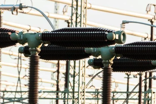
Buck topology offers high efficiency, relative simplicity, and a reduced component count, but it can only step voltage down and its switching behavior imposes constraints on design [S5]. It is a sensible default when the input always exceeds the regulated output and galvanic isolation is unnecessary.
Boost topology supports step-up conversion but similarly cannot regulate an output below the input [S4]. Buck-boost and SEPIC arrangements cover cases where the input may sit above or below the output, while flyback adds transformer isolation at the cost of greater circuit complexity [S4].
On four decision criteria, a buck converter leads on simplicity and low component count, but fails when step-up is required. A boost converter handles step-up but not step-down. SEPIC covers both directions but uses more energy-transfer components. Flyback converters are widely used topologies that serve specific input and output voltage requirements.
The comparison criterion is direct: choose buck for step-down, boost for step-up, buck-boost or SEPIC for variable input direction, and flyback when input-output isolation is required. The engineering trade-off is topology count and switching complexity against the protection, noise control, and installation flexibility gained from isolation [S3][S4].
Wide-Input Trade-Offs and Application Fit
A wide-input converter can reduce spare-part inventory, consolidate purchasing, and limit exposure to shortages, but a single 9–36 V model is not automatically the cheapest solution for every 12 V or 24 V product [S2]. Wide-range products are strongest where the source voltage changes substantially, including automotive batteries, portable equipment, rail systems, and renewable-energy inputs [S2].
Two concrete wide-input families illustrate the electrical range. For rail applications, a converter may operate from 8.5–160 VDC input, providing an 18:1 input range. These ranges support transient-heavy and variable-source installations, but the required external filtering and reduced efficiency at range extremes must be included in the comparison [S2].
Wide-input converters are not the best choice for a fixed, clean laboratory rail, a low-cost application that tolerates a linear regulator, or a design where conduction loss dominates. Conversely, they are well matched to batteries, telecommunications, vehicle electronics, and renewable systems that require voltage accommodation over a broad operating band [S2].
Isolation, EMC, and Safety Boundaries
Isolated converters use a transformer to separate input and output, while non-isolated converters omit that transformer and are generally smaller and lower in cost [S3]. Isolation improves input-output separation and supports noise-control strategies, but it does not eliminate filtering, layout, or component-selection responsibilities [S3].
Design evaluation must cover efficiency, regulation under input variation and load changes, and EMC performance [S4]. The converter should neither be disrupted by interference from nearby circuits nor generate unacceptable interference for adjacent equipment [S4]. In practice, this makes filtering, grounding, component placement, and PCB layout part of the converter specification rather than secondary assembly work [S1][S4].
When evaluating a DC-DC converter, separate the electrical conversion function from the mechanical and electromagnetic system around it. Confirm topology, input range, output regulation, efficiency, isolation, thermal performance, and filter requirements before assigning a part number [S1][S4].
Selection Criteria That Prevent Costly Retests
Begin with the minimum and maximum input voltage, nominal output voltage, maximum output current, and required ripple. A 2:1 range such as 18–36 V supports a 24 V nominal source, whereas an 18:1 range such as 8.5–160 V supports a much broader source [S2]. These limits also determine whether a module, buck, boost, SEPIC, or flyback implementation is viable [S4].
Next, check load behavior, ambient temperature, thermal path, enclosure limits, and efficiency across the operating range rather than at one nominal point [S2]. For inductive or motor-adjacent systems, a variable frequency drive may create conducted and radiated-noise requirements that the converter must coexist with, so an industrial router or controller should specify the required input filtering and grounding interface.
Finally, decide whether galvanic isolation is mandatory or simply preferred. Isolated flyback and related transformer topologies support safety separation and noise isolation, but non-isolated designs reduce component count and footprint when separation is not required [S3]. Record the selected ranges, load points, filter values, and layout constraints before release to production.
The clearest acceptance test is performance across the full input and load envelope: verify regulation, efficiency, output ripple, thermal rise, and conducted or radiated emissions at both input extremes, with component tolerances and PCB variation included.