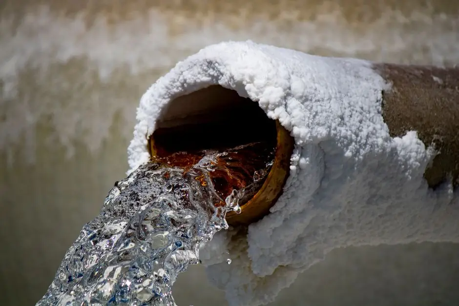
Diaphragm valves cover corrosion-prone chemical dosing, backwash, and filtrate duties, with rubber-lined versions commonly supplied at PN 10 and PN 16 [S1].
For seawater reverse osmosis and multi-stage flash plants, selection must combine chloride-resistant construction, compatible elastomers, pressure-temperature limits, actuator requirements, and maintainable isolation.
Where Diaphragm Valves Fit
Diaphragm valves use an elastomeric membrane to seal against the seat, making them suitable for isolation and throttling where stem leakage and corrosion exposure need to be minimized [S8]. In desalination, their strongest fit is chemical dosing for antiscalant, biocide, acid, caustic, and coagulant service, rather than high-capacity RO feed isolation [S5].
Diaphragm valves used in water treatment and desalination may have ductile-iron bodies with natural-rubber or EPDM linings, while PP or PVDF may be used for chemical service, and their stated pressure class is PN 10 or PN 16 [S1].
The diaphragm valve is therefore a service-specific choice. A chemical dosing valve that handles a few percent antiscalant at low flow is not interchangeable with a seawater isolation valve exposed to chloride, vibration, and high differential pressure.
Material Selection by Fluid
Seawater and brackish RO feed require corrosion-resistant construction such as stainless steel 316 or duplex stainless steel, while chemical dosing may use polypropylene, PVDF, PTFE, PFA, or EPDM wetted components [S1][S5]. Duplex grades UNS S32205 and S32750 offer a higher chloride-resistance option for high-pressure RO equipment [S5].
Elastomer selection must follow the actual chemical rather than a generic seawater label. EPDM is identified for chlorine- and ozone-resistant treated-water service, while PTFE is also listed for ozonated water. Polypropylene and PVDF are preferred for dosing lines carrying alum, PAC, sodium hypochlorite, and lime [S1]. Carbon steel and many elastomers are unsuitable where ozone attack is significant [S1].
For potable applications, the elastomer and protective coating should carry the applicable drinking-water approval, with WRAS, NSF/ANSI/CAN 61, or Indian Standard certification identified as relevant options [S1]. Material claims require confirmation against the exact chemical concentration, temperature, pressure, and oxidant level.
Pressure, Temperature, and Duty
Rubber-lined diaphragm valves for water treatment and desalination are commonly offered in PN 10 and PN 16 pressure classes, with ISO 16138 and EN 13397 identified as relevant standards [S1]. The supplied diaphragm-valve specification lists a pressure class of PN 10 or PN 16 [S1].
Multi-stage flash desalination requires valves that provide corrosion resistance and service suitable for saline and chlorinated water [S1]. By contrast, the documented rubber-lined schedule separates seawater, condensate, and brine discharge services with different diaphragm materials [S3], showing that fluid temperature and chemistry can drive the elastomer choice independently of valve size.
The governing calculation should use maximum operating pressure, design pressure, backpressure or vacuum conditions, water hammer margin, actuator thrust, and the valve’s allowable pressure-temperature rating. A higher nominal pressure class is not a substitute for checking diaphragm deformation, seat sealing, and actuator sizing at the actual differential pressure.
Comparison of Main Valve Options
Diaphragm valves excel at chemical isolation and proportional dosing but are not the default choice for every desalination line. The practical comparison is: [S5]
On chemical compatibility, pressure class, abrasive-solids tolerance, and lifecycle exposure, a lined diaphragm valve is strongest for controlled chemical service; a ball or high-performance butterfly valve is generally stronger for high-flow seawater isolation, and a pinch valve is stronger for abrasive brine [S1][S5].
Configuration and Actuation
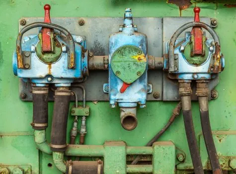
A desalination skid may require on/off, proportional, or modulating operation, with electric or pneumatic actuation selected according to the control signal and plant architecture [S5]. Pneumatic diaphragm actuators can provide fail action, while electric actuators support remote operation without a continuously energized air supply; the required fail position should be written into the instrument and valve datasheet.
Top-entry access can simplify diaphragm and seat inspection without removing the valve from the pipeline [S5]. Verify whether the actuator arrangement permits internal service, diaphragm replacement, and stem re-seating while preserving the valve’s pressure class.
For system-wide control philosophy, compare diaphragm isolation with air-release valves used for pipeline dewatering and air management. They solve different hydraulic problems, and substituting one for the other leaves a functional gap in startup, drainage, or pipeline protection.
Service Boundaries and Failure Modes
Diaphragm valves should not be selected as the default high-pressure RO feed isolation device. In that service, a ball valve may provide a more suitable pressure boundary, while chemical compatibility still depends on the ball, stem, seat, and body materials [S5]. A diaphragm valve is also less attractive where solids repeatedly impact a narrow flow path or where very high-temperature, very-high-pressure service exceeds the elastomer envelope.
Common failure mechanisms include chlorine or ozone attack, swelling from incompatible chemicals, creep and fatigue of the diaphragm, seat compression set, obstructed closure from scale or solids, and external corrosion at unpainted wetted surfaces. The documented MSF schedule uses natural rubber for seawater and butyl rubber for condensate and brine-discharge applications, illustrating why a generic EPDM selection should not be copied across all services [S3].
Residual chlorine exposure is identified up to 5 ppm in treated-water service [S1]. At RO feed, pretreatment, chemical dosing, or post-treatment locations, the specification should state the normal and peak concentration, rather than assuming the seawater chloride level is the only design variable.
Procurement and Acceptance Criteria

The procurement package should identify valve type, DN size, PN or pressure class, body and lining materials, diaphragm compound, end connection, operating temperature, design pressure, allowable differential pressure, flow rate, actuation, fail action, and certification. The documented MSF duty schedule provides three useful specification dimensions: service, body material or lining, and diaphragm material [S3].
For lined valves, ISO 16138 and EN 13397 are identified in the desalination application specification [S1]. Potable-water contact materials should carry an applicable WRAS, NSF/ANSI/CAN 61, or Indian Standard approval [S1]. For severe-duty RO equipment, Duplex UNS S32205, Super Duplex UNS S32750, or Grade 2 titanium may be justified, with selection based on chloride concentration, temperature, crevice geometry, and lifecycle cost rather than a generic material label [S5].
Before approval, compare the quotation against the service fluid, maximum pressure, design temperature, chemical exposure, corrosion allowance, required shutoff, actuator thrust, and maintenance access. Track two procurement signals: confirmation that each wetted material is compatible with the specified fluid, and evidence that the actuator and diaphragm assembly are serviceable without removing the valve from the line.