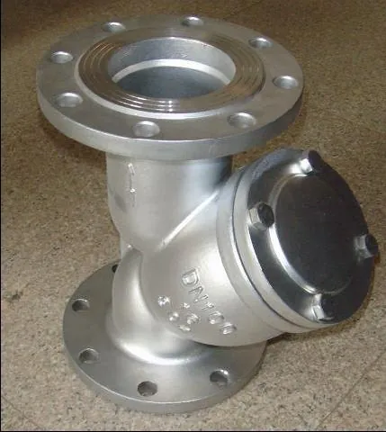
An air release valve is a float operated valve that continuously vents accumulated air out of a pressurized pipeline while the line stays in service. Its working parts are few: a body charged with line water, a float that rides the water level inside that body, and a small orifice at the top, typically 2 to 8 mm in diameter, held closed by a needle seat carried on the float. Air gathers at the body top as line pressure squeezes dissolved and entrained gas out of solution, the water level inside the body falls, the float drops, and the needle opens the orifice. Air escapes to atmosphere at full line pressure until returning water lifts the float back onto its seat. The orifice stays small precisely because the air leaves under pressure: a few dozen cubic meters of free air per hour clears a pipeline high point, while a full bore opening at 10 bar would blast air and water out together and could wreck the float.
Procurement engineers meet these valves on water transmission mains, booster station headers, long process and fire water lines, and wastewater force mains, and they usually buy them as an afterthought after the pumps and mainline valves are chosen. That order of purchase is backwards, because unvented air is what turns a well engineered main into a surging, capacity limited problem. The decision this page settles is narrow and practical: whether a station needs release only, vacuum protection only, or the combination air valve that performs both duties in one body; which orifice diameter clears the air accumulation rate at working pressure; which body construction survives the fluid, from clean potable water to grease laden sewage; and what isolation hardware sits under the valve so it can be serviced without shutting the line down. The answer lands as an RFQ line set sized per AWWA M51 practice and built per AWWA C512, and every chapter below feeds that line set.
This page treats the air release valve as a purchasing object: what the small orifice and float actually do in real numbers, how AWWA M51 sizing converts an air accumulation rate into an orifice drill, where the valve belongs on the line, which body styles survive sewage and freezing, and how orifice, materials, isolation, and vent routing combine into a defensible RFQ. It is written for engineers who issue purchase specifications, not for readers who want a brochure summary.
Chapter 1 / 06
What an Air Release Valve Is and What Is Being Decided
The name is narrower than the family it belongs to, and the distinction is the first thing a specification must get right. An air release valve is the small orifice member of the pipeline air valve family: it vents air that has already accumulated inside a line that is pressurized and in service. Its two siblings are different products. The air vacuum valve, sometimes sold as a kinetic air valve, carries a large orifice, 25 to 50 mm and larger, sized to the valve bore, and it exists for the moments when the line is changing state: it expels bulk air while the pipeline fills and admits air while it drains, so the line neither chokes on air during filling nor collapses under vacuum during draining. The combination air valve puts both orifices in one body and performs all three functions, release under pressure, expulsion on fill, and admission on drain, which is why it has become the default purchase for transmission stations. This page is about the small orifice function, and the types chapter draws the working boundaries between the three products.
Air gets into a pressurized line faster than most specifiers expect, and it arrives by two routes. The first is solution: water carries dissolved air at roughly 2 to 5 percent by volume at the pressures typical of transmission service, and whenever pressure falls, at a summit, on a long dropping slope, or across a throttling station, part of that gas comes out of solution as free bubbles that rise and collect at every high point. The second route is mechanical entrainment: a centrifugal pump running with a vortexing suction, a turbine meter churning on low backpressure, or a line refilled after an outage admits air as bulk pockets. Filling a line that was drained for maintenance introduces the largest single charge, and gravity drainage afterwards can pull a serious vacuum unless air is admitted somewhere, which is a separate orifice doing a separate job.
What the accumulated air costs is measurable and worth stating in the specification narrative that justifies the purchase. A pocket at a high point reduces the effective cross section of the pipe, so friction loss rises and delivered capacity falls; field experience on long mains shows pockets severe enough to cut flow by double digit percentages until they are vented. Entrained bubbles passing a flow meter corrupt the measurement, which is why metering stations are a standard placement for release valves. Trapped pockets also drive surges: a pocket expelling suddenly through a downstream restriction accelerates water columns and produces transients that a pumping station feels as pressure spikes, and the interaction between air pockets and pump trip transients is a documented source of water hammer complaints at high point stations. None of these failure modes show up on a pump curve; they show up as capacity shortfalls and broken equipment after commissioning.
What is actually being decided in this purchase is a set of four commitments. First, the function commitment: release only, vacuum only, or combination, decided from the fill and drain scenarios and the in service accumulation rate, not from habit. Second, the orifice commitment: a drill diameter whose airflow capacity at working pressure exceeds the accumulation rate with margin, chosen from maker capacity tables per AWWA M51 practice. Third, the construction commitment: body and float materials, wastewater geometry if the fluid is sewage, and the vent routing if odor control applies. Fourth, the station commitment: an isolation valve under every air valve, a riser that puts the body at the true high point, and freeze protection matched to the climate. A quotation that answers only the first commitment has priced a widget, not solved a station.
Four standards organize the datasheet, and a buyer should quote them by name. AWWA C512 governs construction and testing of air valves for water service: it fixes standard release orifice sizes from 3 to 12 mm, valve sizes from DN 25 to DN 200 in threaded and flanged executions, pressure classes from PN10 and PN16 through PN40 with high pressure specials to PN100, and the hydrostatic and seat tests the finished valve must pass. AWWA Manual M51, Water Distribution System Air Valves, is the sizing practice: it converts fill rates, drain rates, and dissolved air estimates into orifice selections, and it is the document a supplier's sizing submittal should cite. EN 1074-1 states general fitness for purpose requirements for industrial valves, and ISO 5208 defines the leakage rate classes used when a metal seated needle is tested. A datasheet that quotes none of these four is a price tag, not a specification.
The RFQ should also name the station around the valve, because the air valve never works alone. A full bore gate valve sits between the pipe and every air valve so the body can be serviced without a shutdown, and reduced bore or throttled isolation defeats the air path and is a classic commissioning error. On the discharge side of a booster set, the air valve shares the header with the check valve that protects the pump, a swing check valve on most water mains or a compact dual plate check valve where the spool is short, and on reciprocating or pulsating booster sets a piston check valve is the family usually chosen for that flow. An air valve is never a substitute for a safety relief valve on overpressure duty, and it never replaces the pressure reducing valve that sets downstream pressure on a zone boundary, but both of those stations create the pressure falls that release dissolved air, so air valves belong near them. Stating the whole station in the RFQ lets one supplier check drilling, lining, and orientation compatibility in a single pass instead of four arguments at delivery.
Chapter 2 / 06
How the Float and the Small Orifice Work
Walk one accumulation cycle from a sealed start. In normal service the body stands full of water at line pressure, the float is buoyed to the top, and the needle presses into the small orifice seat, which sits at the highest point of the body. Free air in the line travels up the pipe faster than the water moves, following the crown of the pipe to the high point, entering the body through the lower connection, and collecting under the cover, because the air is lighter than the water it displaces. As the air pocket grows, the water level inside the body falls and the float rides it down. After a few centimeters of travel the float mechanism unseats the needle from the small orifice, and the accumulated air, sitting at essentially full line pressure, expands out through the orifice to atmosphere. The venting continues until water re-enters behind the air, the level rises, the float climbs, and the needle re-seats. Depending on the accumulation rate the cycle may run continuously in slow motion or repeat every few minutes, and the valve needs no power, no signal, and no operator to run it.
The seating behavior is the part worth understanding, because it explains why this design seals tighter as the line pressure rises. When the float is buoyed, the needle approaches the seat from below with the water cushion of the body around it, so there is no slamming. Once the needle touches the orifice, line pressure acts on the float assembly in the seating direction: the higher the pressure, the harder the needle presses into its seat, and the more positive the seal. This is the opposite of the vacuum valve problem, where inward rushing air would fight a closing member, and it is why a release orifice can be trusted bubble tight at high pressure while its seat material is soft. It is also why the minimum sealing pressure appears on the datasheet: a resilient seat seals from very low pressure, while a metal needle on a metal seat needs a pressure assist, commonly a few bar, before the joint is drop tight.
The airflow through the orifice is compressible flow, and one property dominates the sizing: above roughly a 2 to 1 ratio of upstream absolute pressure to atmospheric, the orifice flows choked, so the mass flow of air scales with upstream absolute pressure and stops caring about the downstream side. That is why the capacity tables are read against line pressure. Representative numbers from maker tables: a 5 mm release orifice on a DN 100 combination valve vents roughly 60 to 90 standard cubic meters per hour of free air at 6 bar line pressure, exact figure depending on the maker's seat and vent port geometry. Scale by orifice area: a 3 mm drill moves about a third of that, an 8 mm drill about two and a half times, and a 12 mm drill, the top of the AWWA C512 standard range, close to six times. Every meter of small bore vent piping above the valve adds friction and derates the delivered capacity, which is why tall vent stacks on wastewater installs must be in the sizing calculation.
The sizing logic follows directly: the orifice airflow capacity at working pressure must exceed the rate at which air accumulates at that station, with margin for transients. Estimate the accumulation from solution first. Air in water runs roughly 2 to 5 percent by volume at typical transmission pressures; a DN 600 main moving 1,500 m3/h at 6 bar that climbs over a summit where pressure falls to 3 bar sheds on the order of 1 to 2 percent of flow as free air, call it 15 to 30 standard m3/h arriving at the high point. One 5 mm orifice at 60 to 90 standard m3/h clears that comfortably; two stations spaced along the summit remove any doubt. Entrained air from a vortexing centrifugal pump suction can exceed the solution contribution by an order of magnitude, which is why the station assessment asks how the pump behaves at low wet well levels, not just what the pipe profile looks like.
Fill and drain duty belong to the other orifice, and the sizing rules are velocity rules. When a line fills, the bulk air ahead of the water must leave at the filling rate plus a margin, and practice per Val-Matic guidance sizes the large orifice of the kinetic air valve to handle fill air at up to 5 percent of the water fill velocity converted to air volume flow, with the fill itself controlled at low velocity so the advancing water column cannot compress and then explosively expel a pocket. When a line drains, whether by planned shutdown, a break, or a burst section, the vacuum valve must admit air fast enough to keep the internal pressure above the collapse rating of the pipe, and AWWA M51 walks the drain or burst flow scenario to that admission requirement. A deep well or intake line holds the same physics in miniature: a foot valve at the screen keeps the column in the riser, and the wellhead air valve releases the air column that expands out of solution as the pump draws the riser down on start.
Two mechanism details close the picture for the RFQ reader. Floats are sized with buoyancy margin for the specific body and orifice, so a float from a 3 mm execution does not belong in a 12 mm body, and replacement floats are bought by valve model, not by diameter. And the vent port, the small orifice discharging to atmosphere, is where every failure mode of this product eventually shows up: a continuous hiss means the seat is fouled or the float is waterlogged, a spray means liquid carryover from an oversized orifice or a lost level, and silence at a known high point usually means the isolation valve below was left closed by a maintenance crew. Chapter 6 turns those symptoms into a maintenance program.
Chapter 3 / 06
Types, Construction, and Duty Boundaries
The family splits into three products by orifice architecture, and the split decides what each one can and cannot do at a station. The air release valve, the subject of this page, is the small orifice continuous vent: its orifice runs 3 to 12 mm per the AWWA C512 standard drills, with 2 to 8 mm the common commercial range, and its body is a compact pot, DN 25 to DN 100 typically, that mounts on a riser at the high point. The air vacuum valve, also marketed as the kinetic air valve, carries the large orifice: a full bore opening of 25 to 50 mm and more, sized to the valve inlet, with a float designed to be blown down by escaping bulk air so the opening stays clear during filling and then lifted to close by water. The combination air valve stacks both functions in one body, the small orifice pot above a large orifice base, and performs the triple duty: release of accumulated air under pressure, expulsion of bulk air during filling, and admission of air on draining or vacuum. Buying the right member of the family is the first selection act; the tables and chapters that follow make it a checklist.
Wastewater service is a separate construction world and deserves its own line in the specification. A sewage air valve runs an elongated body with a lower connection shaped so solids are scoured rather than parked, a float whose travel wipes the body walls clean of grease, and an outlet sized for the venting duty, routed to atmosphere through an odor scrubber or carbon canister rather than left open, because force main air is a neighbor complaint in waiting. Clean water bodies can mount in any orientation that keeps the float axis vertical; wastewater bodies are orientation sensitive, and the maker's drawing governs. In cold climates the whole assembly, body plus isolation, either buries below frost line in a drained vault, sits in an insulated cage above ground, or carries heat trace, because a frozen float pot cracks quietly in January and announces itself in June.
Materials and pressure ranges follow the fluid and the line. Bodies come in ductile iron with fusion bonded epoxy lining for potable and raw water, cast steel for industrial and higher pressure service, and 316 stainless for corrosive and high purity duties, including most wastewater and many chemical water circuits. Floats are 316 stainless or epoxy coated cast iron in water service, with solids wiping profiles in sewage. Seats and needles run Buna-N or EPDM resilient inserts for bubble tight low pressure sealing, or 316 stainless for grit and high temperature. Valve sizes run DN 25 to DN 200 with threaded ends below DN 50 and a flange from DN 50 up, in PN10 and PN16 standard classes through PN40, with high pressure specials to PN100 on request for deep transmission and feed lines. On large diameter stations the companion isolation for the mainline is often a butterfly valve, while the air valve isolation itself stays quarter turn and full bore.
The table below consolidates the family into the form a specifier can scan before writing the RFQ.
Family member
Orifice architecture
What it does
Where it belongs
Air release valve
Small orifice, 3 to 12 mm per AWWA C512, 2 to 8 mm common
Vents accumulated air continuously while the line is pressurized and in service
High points, pump discharge headers, upstream of meters and control valves, dropping slopes
Air vacuum valve, kinetic air valve
Large orifice, full bore 25 to 50 mm and larger, sized to inlet
Expels bulk air during filling, admits air during draining to prevent vacuum collapse
Fill and drain points, long ascents and descents, deep well heads, pipeline ends
Combination air valve
Both orifices stacked in one body
Triple function: release under pressure, expel on fill, admit on drain
The default station valve for most transmission mains and booster headers
Wastewater combination valve
Both functions in an elongated body with solids wiping float
Same duties in sewage and grease service, vent routed to odor scrubber
Force main summits, lift station headers, anywhere the fluid is not clean water
Boundaries against hardware that gets confused with this family should be stated once, plainly, in the specification narrative. The air valve vents accumulated gas from a pressurized closed line; it is not a conservation vent for an atmospheric tank, whose breathing duty belongs to a tank breather product discussed in the selection chapter. It provides no overpressure protection of any kind, and no pressure regulating function of any kind, and the chapters that follow assume those duties are covered by hardware built for them. It is also not a debris device: the orifice is the smallest flowing passage at the station, and grit that reaches it came through a line that needed better commissioning practice, a point the maintenance chapter returns to with the strainer hardware that protects the rest of the station.
Chapter 4 / 06
Key Specification Parameters
The table below decodes the datasheet lines that decide whether a quoted air valve matches the station. Each row is purchase defining; the paragraphs after the table explain what to demand and what a weak answer looks like.
Attribute
Typical range or options
What it decides
Valve inlet size
DN 25 to DN 200, threaded below DN 50, flange DN 50 up
Riser size and flange drilling; never assumed equal to the main size
Release orifice
2 to 8 mm common, 3 to 12 mm AWWA C512 standard drills
Air clearance rate at working pressure, the core sizing row
Working pressure
PN10 and PN16 standard, PN25 to PN40 range, specials to PN100
Shell rating and the float buoyancy design pressure
Body material
Ductile iron epoxy lined, cast steel, 316 stainless
316 stainless or epoxy coated cast iron, solids wiping shapes for sewage
Corrosion life and reliable level sensing in the actual fluid
Seat and needle
Buna-N or EPDM resilient insert, or 316 stainless metal seat
Minimum sealing pressure and the leakage rate achieved
Airflow capacity
Maker table at stated pressures, e.g. 5 mm at 60 to 90 std m3/h at 6 bar
Whether the orifice outruns the accumulation rate with margin
Minimum sealing pressure
Near zero on resilient seats, several bar on metal needles
Drop tight behavior at the low pressure end of the station envelope
The airflow row deserves the most attention because it is the row most often left vague. A quotation that states an orifice diameter without a capacity figure has not answered the sizing question: what matters is standard cubic meters per hour of free air delivered at the station's working pressure, read from the maker's table, then derated for the vent piping above the valve. The representative capacities below are computed for a sharp edged orifice at 15 deg C and rounded; maker tables govern, and long vent stacks derate them further.
Release orifice
Free air at 2 bar, std m3/h
Free air at 6 bar, std m3/h
Free air at 10 bar, std m3/h
3 mm
10
25
38
5 mm
28
75
100
8 mm
70
160
250
12 mm
155
365
570
What the datasheet must state, beyond the tables, is the evidence chain. AWWA C512 requires hydrostatic testing of the shell and a seat test at working pressure; the submittal should name both. ISO 5208 leakage rates apply when a metal seat is quoted, and the rate achieved should be written on the test certificate, not assumed. Material certificates to EN 10204 3.1 belong on stainless and wastewater bodies, and the epoxy lining on ductile iron should be named by thickness and coating standard. The minimum sealing pressure, several bar on metal needle seats, must be stated and checked against the lowest pressure the station will ever see, because a transmission line that pressure cycles between 2 and 10 bar needs a seat that seals at both ends.
The joint from valve to riser is its own small specification. The flange drilling follows EN 1092 or ASME B16.1 and B16.5 depending on the yard standard, the facing matches the riser, and the gasket is an EPDM or compressed fiber grade rated for potable contact and the station temperature, replaced at every body service because a hardened gasket is the most common leak path on an otherwise sound install. Threaded ends below DN 50 take sealant rated for potable water and should still sit under an isolation valve. None of this is exotic; all of it is forgotten exactly often enough to deserve RFQ lines of their own.
One sizing honesty note closes the chapter. An oversized orifice does not buy safety, it buys water carryover: when the air pocket is small, a large orifice begins spitting water before the float re-seats, and on a tall vent stack that spray lands on whatever is below. The correct orifice is the smallest drill whose capacity at working pressure clears the accumulation estimate with margin, stepped up one standard size when the station assessment is uncertain. That rule, applied at RFQ stage, prevents the two most common commissioning complaints about this product: the undersized valve that cannot keep up, and the oversized one that rains on the pump station.
Chapter 5 / 06
Selection Decision Factors and RFQ Language
Placement comes before sizing, because a perfectly sized valve at the wrong station vents nothing. The working rules, consistent across AWWA M51 practice and maker application guides, read as follows. Put a valve at every high point, and prefer a summit where the pipe rises at 45 degrees or steeper: the steeper the summit, the more surely the air funnels to one point instead of stringing along a gentle crown. Space valves every 400 to 800 m on long horizontal runs, because air migrates slowly on flat pipe and collects in stretches between summits. Put one at pump discharge headers, where entrained air enters the system and where the vacuum function protects against column separation on trip. Put one upstream of every flow meter and control valve station, because entrained air corrupts the measurement and upsets the control. Put them on long dropping slopes, where the pressure keeps falling and dissolved air keeps coming out of solution along the entire descent. And put one at the ends and dead legs where fill and drain air enters and leaves in bulk.
The station hardware under the valve is a selection item, not an afterthought. Every air valve sits on a full bore isolation valve, a gate valve at most sizes or a ball valve on the small inlets, and the bore must be full: a reduced bore or half open isolation throttles the air path, derates the capacity calculation, and hides the fact from everyone except the surge analyst. On the large diameter mains where the nearest line isolation is a butterfly valve, the air valve station keeps its own quarter turn isolation regardless, because the valve service crew must never depend on a line shutdown to clean an orifice. The isolation valve is exercised on the maintenance schedule like any other, because a seizure discovered during an air valve failure doubles every outage. Where the fluid carries debris, the station plan should acknowledge the strainer hardware elsewhere on the line, a Y strainer on small pump suction and instrument lines or a basket strainer on larger suctions, whose job is keeping grit out of everything downstream, including the orifice that this page keeps calling the smallest passage at the station.
Sizing runs as a two step estimate per station. Step one, in service accumulation: dissolved air at 2 to 5 percent by volume, plus entrained air from the pump suction behavior, converted to free air at the local pressure, gives a standard m3/h figure arriving at the station. Step two, capacity: pick the smallest orifice from the maker table whose delivery at working pressure clears step one with margin, per the M51 method. For the fill and drain states, size the large orifice of the vacuum or combination valve on the fill air rule, up to 5 percent of water fill velocity as free air flow per Val-Matic guidance, and on the drain or burst scenario that sets the admission requirement. A DN 100 combination valve with a 5 mm release orifice venting 60 to 90 std m3/h at 6 bar covers most DN 300 to DN 800 transmission stations outright; the exceptions are big mains with steep pressure falls and sewage lines with heavy gas generation, both of which justify the next orifice step.
The boundary against neighboring hardware belongs in this chapter, stated plainly so nothing in the specification double counts duties. The pressure vacuum relief valve is a tank breather, a conservation vent fitted to atmospheric storage tanks to hold the vapor space within a few millibars of ambient; it breathes with tank filling and emptying and weather changes, and it is never a pipeline high point vent, because a transmission main at 6 bar would hold its pallets wide open and vent the line to atmosphere. The safety relief valve protects equipment against overpressure and has no air removal function at all. The back pressure regulator sustains a minimum downstream pressure in the line, a duty it shares with other pressure hardware, but no regulator of any kind can remove air, because air at a high point is not a pressure problem, it is a gravity problem: the bubbles sit where the water will not carry them, and only a vent at that point removes them. A zone or pressure reducing valve station is, in fact, a place where air comes out of solution immediately downstream as pressure falls, so the correct pairing is a pressure reducing valve skid with an air valve station just downstream of it.
Selection against the check valve hardware on the same header is a matter of stations, not competition. The air valve vents the header; the check valve family protects the pump: a swing check valve remains the water main default at moderate sizes, a dual plate check valve wins where the spool between flanges is short and weight matters, and a piston check valve handles the pulsating discharge of reciprocating boosters that would chatter a swing. At the wet well, a foot valve on the intake keeps the suction column for the pump, while the wellhead air release valve handles the air that comes out of that column on every start. The air valve specifier who names these neighbors in the RFQ gets a station that works as a system; the one who buys the valve alone gets a valve that works while the station does not.
The application map below turns the placement and construction rules into a table the project file can carry.
Application
Construction to specify
Check before order
Transmission main summit, DN 300 to DN 1400
Combination air valve per M51 charts, epoxy iron or 316 body, full bore isolation below
Orifice airflow against accumulation at working pressure; vent stack derate
Booster station discharge header
Combination valve with vacuum function beside the check valve station, surge review included
Fill and drain air rates; pump trip column separation
Upstream of a flow meter or control valve
Release valve, small orifice only, mounted close coupled on the upstream spool
Entrained air estimate; meter error tolerance
Wastewater force main summit
Wastewater combination valve, elongated body, vent piped to odor scrubber
Grease fouling schedule; float access; orientation per maker drawing
Deep well or intake riser
Wellhead air valve sized to the column, intake foot valve at the screen
Air release on start; vacuum admission on shutdown
Release valve, epoxy iron body, station protected by a duplex strainer on the pump suction
Fouling service intervals; freeze protection in exposed plants
Long dropping slope, pressure falling
Release valves spaced along the descent per profile study
Solution air released over the run; spacing 400 to 800 m rule check
The RFQ block should be written once and reused. A complete block reads: quantity and station list with pipe profile attached; function per station, release, vacuum, or combination; inlet size and orifice drill with the maker capacity table quoted at two pressures; maximum and minimum working pressure, including the minimum sealing pressure of the quoted seat; fluid description, potable, raw, sewage, or process; body, float, and seat materials with lining and certificates; ends and drilling standard with the gasket grade; isolation valve type and bore; vent routing requirement including odor scrubber where sewage; freeze protection class for the climate; and the evidence set, AWWA C512 construction with hydrostatic and seat tests, ISO 5208 rate where metal seated, EN 10204 3.1 certificates on stainless, and the M51 sizing submittal showing the accumulation estimate behind every orifice chosen. A quotation returned without the capacity table or the sizing submittal is incomplete at any price.
Chapter 6 / 06
Installation, Standards, Failure Modes, and Maintenance
Installation quality decides whether the valve ever sees the air it was bought to remove. The riser must reach the true high point of the pipe, not the convenient point, because air collects at the crown geometry, not at the nearest structure; on summit stations a 45 degree or steeper profile delivers the air to one point, and the riser stands there, vertical, with the body upright so the float axis is plumb. Vaults that house the assembly are drained, vented, and sized for a technician with tools, and in frost climates the assembly buries below the frost line, sits in an insulated cage above ground, or carries heat trace, chosen by climate class and written into the RFQ rather than improvised by the contractor. The isolation gate valve or ball valve under the body is installed with its stem accessible and is exercised on the same schedule as the rest of the station. The vent outlet faces down or is shielded, so rain and insects stay out of the orifice, and a tall vent stack on a wastewater install slopes its piping to a drain and keeps its friction loss in the capacity calculation.
Wastewater installs add three practices of their own. The vent line runs to an odor scrubber or carbon canister sized for the gas generation rate, with a condensate drain at the low point of the run, because a vent line that traps condensate blocks the very gas path it exists to provide. The body mounts in the orientation the maker's drawing shows, since the elongated wastewater body scours by shape and misalignment parks solids. And the assembly gets genuine access, because sewage air valves are cleaned on a schedule, not on a theory. The conservation vent duty of a pressure vacuum relief valve on an atmospheric tank is a neighbor's job with its own mounting rules; nothing about a tank breather installation transfers to a pipeline station, and the two should never share a submittal.
The failure modes of this product are few, well understood, and mostly curable in place. Orifice fouling is the leader: iron bacteria, manganese, and grease build on the needle and seat until the valve hisses continuously or fails to close, and the cure is periodic cleaning of the needle seat, on a quarterly to annual interval set by the fouling rate observed. Float corrosion or waterlogging is second: a pinholed float fills, sinks, and holds the orifice open, spraying water until the float is replaced; floats are consumables and are bought per valve model. Leakage past a worn seat shows as a fine mist at the vent and is cured by lapping or replacing the seat, with the valve tagged for shop work if the seat is integral. Freezing cracks bodies and floats in unheated vaults, prevented by the climate measures above, or cured by draining before winter if the station is seasonal. Two system level failures complete the list: vacuum collapse of the pipeline when the vacuum function is missing or undersized, prevented by sizing the air vacuum valve to the drain and burst scenario per M51, and water hammer from trapped air pockets at high points driving surges through a pumping station, prevented by expelling the air, controlling the filling velocity, and reviewing the pump trip case with the air volumes actually present.
The maintenance program is short enough to run on a card. Monthly or quarterly, walk the stations and listen: a steady hiss says fouled seat or sunk float, silence at a known high point says closed isolation, and either finding is a same day work order. Annually in fouling service, or on the maker's interval in clean water, isolate, depressurize the body, and clean the needle and seat; inspect the float for coating damage and buoyancy; replace the body gasket at reassembly because a reused gasket is the most common leak after service. Keep spares per station set: one float, one seat kit, one gasket set, and one complete valve for critical single station lines. The debris that kills orifices usually entered during commissioning, so the record should note whether the line was flushed properly and whether the station's Y strainer and the pump's basket strainer or duplex strainer were cleaned after startup, because that history predicts the fouling interval better than any table in this page.
Close the lifecycle with records the next RFQ can use. Keep the station list with the as-built profile, the sizing submittal with its accumulation estimates, the maker capacity tables quoted, the test certificates, and the maintenance log with dates and findings in one file per line. When the next line is specified, that file converts supplier opinions into line items: measured fouling intervals set the cleanability requirements, observed carryover sets the orifice step, and freeze history sets the climate class. A line that logs air problems at a high point will not be cured by a back pressure regulator or any other pressure hardware added after the fact; the air must be vented where it collects, and the file that proves it is how a purchasing specification gets smarter instead of just older.
FAQ
What is the difference between an air release valve and an air vacuum valve?
An air release valve is the small orifice member of the family: it vents air that has accumulated inside a pressurized, in service pipeline through an orifice of typically 2 to 8 mm, governed by AWWA C512 drills of 3 to 12 mm. An air vacuum valve, also called a kinetic air valve, carries a large orifice of 25 to 50 mm and larger that expels bulk air while the line fills and admits air while it drains. A combination air valve performs both duties in one body.
How do I size the release orifice for my pipeline?
Estimate the free air arriving at the station, then pick the smallest orifice whose capacity clears it. Dissolved air in water runs roughly 2 to 5 percent by volume at typical pressures, so a pressure fall at a summit releases a share of flow as free air; add entrained air from the pump suction. Then read the maker capacity table at working pressure: a 5 mm orifice vents roughly 60 to 90 standard m3/h at 6 bar. Capacity must exceed accumulation per AWWA M51.
Where should air valves be installed along a pipeline?
At every high point, ideally a summit of 45 degrees or steeper where air funnels to one spot; every 400 to 800 m on long horizontal runs; at pump discharge headers; upstream of flow meters and control valves, because entrained air corrupts measurement; and along long dropping slopes where falling pressure keeps releasing dissolved air. Fill and drain points, dead legs, and well heads need the vacuum or combination function for bulk air handling.
Why does my air release valve spit water at the vent?
Water carryover usually means the orifice is oversized for the actual accumulation rate: when the air pocket is small, a large drill starts passing water before the float re-seats. Other causes are a float that has partially flooded and sits too low, a vent line with friction losses that slow the air enough for water to arrive first, and a station that is a low point collecting water rather than a true high point. The fix is the correct orifice step, a float replacement, or relocating the riser.
Does every air valve need an isolation valve below it?
Yes, and it must be full bore. The isolation valve, typically a gate valve or a ball valve, lets the body be cleaned, re-seated, or replaced without shutting the line, and every maintenance schedule depends on it. A reduced bore or partially open isolation throttles the air path, silently derates the orifice capacity, and defeats the sizing calculation. Exercise it on the station schedule so it works the day it is needed.
Can an air release valve prevent vacuum collapse or water hammer?
Not by itself. Vacuum collapse is prevented by the air vacuum function, the large orifice admitting air at the drain or burst rate sized per AWWA M51, which is why combination valves are the default purchase. Water hammer from trapped air is reduced by expelling the air at high points and controlling the filling velocity, but the pump trip transient itself needs the check valve and surge hardware reviewed with the actual air volumes included. The release orifice only removes accumulated air under pressure.
What construction is needed for wastewater or freezing service?
Wastewater air valves use an elongated body that scours solids, a float that wipes grease from the walls, and a vent routed to an odor scrubber or carbon canister with a condensate drain; 316 stainless construction is standard for sewage. For freezing climates, bury the assembly below the frost line in a drained vault, use an insulated cage above ground, or heat trace the body and isolation, chosen by climate class and written into the purchase specification rather than improvised after the first cracked float.