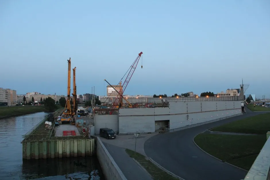
A Hydrofraise is the stronger technical choice for diaphragm wall panels below 50 m where rock, hard ground, or stringent verticality governs, while a hydraulic grab remains economical in suitable soil.
The comparison covers excavation method, depth capability, spoil handling, verticality, suitable ground conditions, plant requirements, and the decision threshold below 50 m.
Depth and ground conditions decide the method
A diaphragm wall is a reinforced concrete curtain constructed by excavating a slurry-supported trench, installing reinforcement, and concreting through a tremie. Wall thickness varies between 0.6 and 1.1 m, and panel widths are between 2.5 and 6 m [S5].
That is an application range, not an automatic machine rating: the contractor must verify tool capacity, crane working chart, slurry performance, joint details, and the panel geometry proposed for the site.
Grabs are effective in soil and very weak rock. They become slow and can generate unacceptable vibration when rock or hard layers must be broken, particularly if chiselling is added [S1].
Hydrofraise uses slurry circulation, not direct spoil lifting
Hydrofraise excavation differs fundamentally from grab excavation. The reverse-circulation process therefore uses the slurry for trench stability and spoil transport at the same time.
For the diaphragm wall grab comparison, this means Hydrofraise excavation is less directly constrained by the depth-related lifting burden that applies to a suspended grab.
The method is intended for rock, hard soil layers, deep panels, and projects with strict construction tolerances [S3]. It is not merely a larger grab: it requires cutter selection, reverse-circulation piping, slurry control, desanding capacity, and an operational method suited to maintaining panel geometry.
Verticality, panel geometry, and production trade-offs
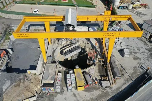
These figures describe excavation tolerance capability, not panel length or total wall alignment.
That tolerance can materially reduce accumulated alignment error over a panel approaching 50 m, but it must be demonstrated by the actual machine, guidance package, and site-specific operating procedure.
Hydrofraise excavation can also reduce depth-related loss of excavation rate because the tool is not directly lifting spoil [S1]. However, production is not independent of logistics: reverse circulation moves a greater fluid volume, and the returned slurry requires controlled desanding and desilting [S3].
A project-specific comparison for a 50 m panel should therefore test verticality over the full panel, not just the cutter head. The detailed engineering topic Set Diaphragm Wall Grab Verticality by Depth is relevant when developing the alignment acceptance criteria for deep excavation.
Hydraulic grab versus rope-operated grab
Its verticality benefit comes from hydraulic guide systems and associated monitoring instrumentation.
It remains a direct mechanical excavation system, so the tool must physically enter and remove material panel by panel. Below 50 m, suitability depends on the specific grab, crane, operating weight, and ground resistance.
The selection matrix is straightforward: choose a hydraulic grab for compatible soil, efficient crane handling, and a moderate verticality requirement; choose a rope grab when its capacity is proven for the ground and simpler operation is preferred; specify Hydrofraise where rock, hard layers, greater depth, or tighter verticality control outweigh plant and slurry-processing complexity.
Selection criteria for panels below 50 m
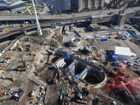
Depth below 50 m does not by itself invalidate a grab. Published guidance lists 50 m as a typical depth for walls constructed by a grab and up to 100 m for Hydrofraise construction [S3]. A grab at 45–50 m remains defensible when the soil is suitable, the crane and grab are rated for the duty, and the contractor has demonstrated acceptable excavation and alignment performance.
Hydrofraise becomes the preferred option when any of four conditions applies: competent rock or hard interbeds are present; chiselling would slow the grab and create unacceptable vibration; required panel verticality is tighter than the hydraulic grab can demonstrate; or site logistics favor circulation-based spoil removal over repeated mechanical excavation [S1][S3].
Hydrofraise is not automatically the better choice for every deep panel. It adds cutter and reverse-circulation complexity, requires high-capacity slurry treatment, and may be less economical in soft ground where a hydraulic grab can excavate efficiently. Contract pricing should compare complete cycle time, slurry loss and treatment, plant mobilization, power requirements, and the risk of vibration or refusal in hard strata.
Jointing, reinforcement, and slurry risks remain critical
Deep excavation increases the importance of panel joints. A published patent document states that panel jointing systems have not kept pace with grab development and identifies reluctance to use certain systems as depths increase above 30 m [S7]. This is a design warning, not proof that a particular joint is unacceptable, but it requires an explicit assessment of water bars, stop ends, excavation tolerance, and joint continuity.
Stop ends with vertical water bars are used to form watertight joints between diaphragm wall panels [S3]. The open trench must remain supported by bentonite or polymer fluid during excavation, cage installation, and concreting, and the slurry's physical and chemical properties must be monitored [S3].
Reinforcement installation and tremie concreting impose separate deep-panel checks. The cage must be lowered without damaging the slurry-supported excavation, and concrete must be placed in one uninterrupted operation while tremie pipes remain embedded in fresh concrete [S3]. Equipment selection should therefore be assessed as a complete excavation, slurry, reinforcement, and concreting system rather than as a cutter-depth comparison alone.
Procurement and quality-control requirements
Specify the excavation method against measured ground conditions, including soil consistency, rock strength, hard layers, groundwater pressure, and required panel tolerance. Do not accept a nominal depth range as proof of capacity: for Hydrofraise, confirm cutter suitability, crane and suspension capacity, reverse-circulation flow, desanding capacity, and excavation guidance; for a grab, confirm tool length, weight, closing force, crane chart, and performance in the expected material [S1][S3].
For a hydrofraise production case, the HC05 machine described in an Auckland technical paper worked efficiently from 6.5 m and installed panels up to 40 m deep [S1]. The documented project panels were 630 mm thick and averaged 17 m deep [S1]. That evidence supports the method in the reported ground, but it does not establish a universal rating for a 50 m panel.
Quality control should combine survey of excavation verticality, instrumented guidance where available, slurry density and sand-content checks, returned-solids inspection, and verification of the panel bottom before cage placement. The source material identifies hydrofraise guidance systems and monitoring instrumentation as central to improved control [S1].
Recommended equipment basis for a sub-50 m panel
For a sub-50 m panel in soil or very weak rock, select a hydraulic grab when the tool capacity, crane working chart, and verticality acceptance criteria are demonstrated. A rope-operated grab remains viable where the ground is compatible, but its 1 in 100 verticality tolerance is less favourable than the 1 in 150 hydraulic guidance basis cited for hydraulic grabs [S1].
Select Hydrofraise where the ground investigation indicates rock or hard layers, a grab would require chiselling, or the project needs the lower verticality deviation available from hydromill excavation. The cited hydromill figure is below 0.3% [S4], while published diaphragm wall guidance associates Hydrofraise with deep panels, hard ground, and strict tolerances [S3].
Before purchase or subcontract award, require the contractor to submit a 50 m-class panel execution method covering verticality over the complete depth, slurry density and stability, reverse-circulation and desanding capacity, cutter or grab selection, crane duties, joint installation, cage clearance, and tremie concreting. Do not make the final choice from excavation depth alone.